Hi all,
I build a small amp based on a TDA7240 chip. I followed the data sheet and the only difference is I didn't implement the standby switch.
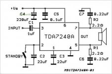
This is the schematic of the circuit:

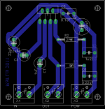
And this is the PCB I made:

The circuit is powered by a 9V AC toroidal transformer followed by a bridge rectifier providing thus an unregulated 11-12V DC to the circuit.
When I power-on or off the amp there is a bump not really loud but the woofer's cone moves suddenly by several mm. As can be seen from the schematic there is not a clearly marked + and - output, so depending how I connect the two output wires to the speaker, the movement is out at power-on and in at power-off, or reversed if I reverse the wires.
Apart from this on and off problem, the amp seems to work flawlessly, but I don't want to damage the speaker, what could be the possible cause and how can I avoid it?
Thanks in advance for any suggestions.
The complete TDA7240 data sheet is here: TDA7240, and the power switch is a simple DPST one that breaks both live and neutral followed by a fuse.
Ralf
I build a small amp based on a TDA7240 chip. I followed the data sheet and the only difference is I didn't implement the standby switch.
This is the schematic of the circuit:
And this is the PCB I made:
The circuit is powered by a 9V AC toroidal transformer followed by a bridge rectifier providing thus an unregulated 11-12V DC to the circuit.
When I power-on or off the amp there is a bump not really loud but the woofer's cone moves suddenly by several mm. As can be seen from the schematic there is not a clearly marked + and - output, so depending how I connect the two output wires to the speaker, the movement is out at power-on and in at power-off, or reversed if I reverse the wires.
Apart from this on and off problem, the amp seems to work flawlessly, but I don't want to damage the speaker, what could be the possible cause and how can I avoid it?
Thanks in advance for any suggestions.
The complete TDA7240 data sheet is here: TDA7240, and the power switch is a simple DPST one that breaks both live and neutral followed by a fuse.
Ralf
Attachments
I don't know how to, or if the amplifier can mute it's input/output when starting up or shutting down.
If it cannot be made quiet during ON/OFF then I suggest you add a speaker protection relay in series with one of the speaker feeds after the output Zobel.
This relay should have delayed ON and instant OFF.
It would be nice if it also had DC detect and trigger OFF.
I recommend adding a 1M0 across input to signal ground. And to parallel this with a 47pF (maybe as high as 1nF) capacitor for RF attenuation.
Last edited:
I don't think it can.I don't know how to, or if the amplifier can mute it's input/output when starting up or shutting down.
Can you recommend a circuit? As for powering the circuit I have 9V AC or +12V DC (I don't have -12V DC).If it cannot be made quiet during ON/OFF then I suggest you add a speaker protection relay in series with one of the speaker feeds after the output Zobel.
This relay should have delayed ON and instant OFF.
It would be nice if it also had DC detect and trigger OFF.
Do you mean adding the resistor and cap between pin 1 and 2 on the X1 connector? Pin 1 is signal ground and pin 2 is signal input.I recommend adding a 1M0 across input to signal ground. And to parallel this with a 47pF (maybe as high as 1nF) capacitor for RF attenuation.
Thanks, Ralf
So can I simply add a switch between the leg from pin2 to the cap C2 and the left ground path (referring to the pic of my PCB)?Why not implement the standby switch, that's why it is there, to avoid on/off transients.
You need a simple switch and a 22uf cap connected to pin2
Use the "stand-by" instead of a traditional "power switch"
When is the amp in standby? With this switch open?
Thanks, Ralf
So can I simply add a switch between the leg from pin2 to the cap C2 and the left ground path (referring to the pic of my PCB)?
When is the amp in standby? With this switch open?
Thanks, Ralf
Yes.
")
Yesterday I did a quick test using just some wires, alligator clips and a switch, implementing the standby part of the circuit.
I can say it works: I firstly switched on the main power-on switch and then the standby switch, without the bump. Reverse operation for powering off.
I must add that the amp is in standby when the standby switch is closed, so I had to reverse "logically" the switch: now it indicates on when the switch is actually open.
So now it's time to make 2 more holes in the already populated PCB and connect permanently the new switch.
Ralf
It's no "problem", that's how the chip was designed. It is never completely "off" so long as the device is plugged in. "Off" is actually "standby". That's how a lot of modern devices are setup.
Speaker protection however is optional, I'm not for, or against it.
I would not bother on this type of project unless you have some expensive speakers to protect, or educational purposes.
Speaker protection however is optional, I'm not for, or against it.
I would not bother on this type of project unless you have some expensive speakers to protect, or educational purposes.
I have an update. Unfortunately the problem is there yet, but more subtle.
I added a switch for the stand-by function, and I found that doing so I effectively eliminated the noise associated with power-on and off. What I didn't notice with my first try (with a crap speaker with heavy grilles), is that when I go from stand-by to on the woofer moves suddenly but without noise, and when I go from on to stand-by nothing happens (no noise, no unexpected woofer movement).
Any ideas?
Thanks, Ralf
Minor problem with speaker protection circuits - outputs are sitting at half the supply voltage, not ground (bridged output amp) so most off the shelf protection circuits won't work with out a bit of dithering with them.
Also, when checking DC levels, you must compare both outputs to each other and if there is a significant difference, then probably problem in the chip.
Also, according to the spec sheet making C1 larger reduces pops . Also, if C1 is polarised, make sure the plus end goes to the chip (I would use film type caps to eliminate that worry - YMMV). (all the electrolytics should have + connected to the chip, others have negative to ground.) Good luck with it.
Last edited:
I tried what sregor suggested.
I added in parallel to C1 another 1uF cap for a total of 2uF, then a 2.2uF one for a total of 3.2uF. The woofer movement remains, what change is the delay between the switch-on and the movement, delay greater with greater C1 value.
As I said before there isn't any audible pop (using the stand-by switch to bring on the amp), only the big woofer movement.
I think there is time to find a speaker protection circuit, the problem is that I wasn't able to find one that is suitable to a bridge amp coupled with an asymmetrical power supply 12V-ground.
Another option that I could try is to use this simple circuit to provide a small delay: Power Amplifier Speaker Protection Circuit Schematic. What do you think? What coil voltage for the relay should I use with a 12V DC power supply?
Thanks, Ralf
the list of parts says 9V 500 ohm relay.
That is what You need.
Choose a high current relay.
Would be nice if it was a 2 state relay , with no power applied it should connect a 10-20 Kohm resistor across the output of the amplifier, and when it is under power it should connect Your speaker.
That will solve the problem for sure.
That is what You need.
Choose a high current relay.
Would be nice if it was a 2 state relay , with no power applied it should connect a 10-20 Kohm resistor across the output of the amplifier, and when it is under power it should connect Your speaker.
That will solve the problem for sure.
Yes, I've seen that. I was just wondering why with a 12V power supply you need a 9V relay. How critical is the nominal voltage and resistance of the coil?the list of parts says 9V 500 ohm relay.
That is what You need.
With C1=1uF (nominal value), the woofer moves after a very short delay, I think less than 0.5 sec it is very short but noticeable. Increasing C1 up to 3.2uF the delay reach some 1 sec. I'll try modifying C2.How long is the turn on delay?
Thanks, Ralf
Last edited:
- Status
- This old topic is closed. If you want to reopen this topic, contact a moderator using the "Report Post" button.
- Home
- Amplifiers
- Chip Amps
- Problem with power-on and off