I wanted to share the joy here and let everyone know about this cheap 2-channel full-range mini-plate-amp that is available from ApexJr and on Ebay. These are great for DIY active speakers, if you are in to that kind of thing, or as a low-medium power chip amp that you can put to use for computer speakers, or whatever your DIY heart desires.
The HTA-2000 was originally intended as a PA or karaoke amp. It's a small full range plate amp with several inputs, fusing, etc. and puts out about 25W/ch using the transformer that the manufacturer intended. It uses a Sanyo STK-4141V chip amps, which is a 2-channel unit. The datasheet for the 4141V and (more importantly) the schematic for the entire amp are available online (I have posted links below) so you can see what you are getting into.

What I like about this is:
A. It's small and inexpensive!
B. 25W+ per channel is plenty for moderately efficient speakers
C. The amp is quiet - it's difficult to tell it's on, very low noise
D. Distortion performance is acceptable (0.08% into 8 ohms and 0.2% into 4 ohms) - see post#3 for more details on this
E. It has 2 channels, perfect for a small DIY active speaker/monitor
F. It has onboard +/- 12VDC easily accessible via a connector, enough to power relays or line-level circuits. Alas this doesn't provide the cleanest DC power so it's best used for non-audio needs like LEDs or relays, etc.
G. You can use a range of transformers, to take advantage of the 4141V's capabilities if you want a little more power, up to 50-60W/ch into 8 ohms.
H. When the OEM transformer is not available, there is a good low-cost alternative
I. You can opt to only use the chip amp portion of the HTA-2000 and leave the preamp-level circuitry dead.
J. It's easy to disassemble in order to remove the parts of the amp that you aren't going to use.
K. As noted on the ApexJr page, you can bridge these for about 80W total into 8ohms (stick to low frequencies, however!), so this could be a nice, cheap small subwoofer amp.
I could probably come up with a few more plusses...
In the minus column:
1. You will need to do a little DIY-ing, but isn't that why we are all here?
2. The +/-12V "regulated" supply is poorly designed and can not deliver much current (I estimate 20-30mA).
3. There is some odd power-down behavior. When you throw the off switch the amp initially shuts off (in about 0.5 sec) but then the audio comes back on again as the PS finally drains after about 20-30 seconds, until the PS is exhausted. No big deal, really. This is where a couple of relays would be a nice use of the 12V supply, to disconnect the speakers on shut down.
4. The op amps in the pre-amp section are 1448 types, which have poor performance. Luckily you can bypass this and connect directly to the power amp section.
Here are some relevant links to check out:
HTA-2000 amp at ApexJr
HTA-2000 amps for sale on Ebay
Sanyo STK 4141v Datasheet
Note that ApexJr also sells the OEM transformer, but the Ebay seller does not. ApexJr has an inexpensive toroidal transformer, 42VCT 80VA for $10 ea, that is perfect with these amplifiers (I just tested one).
-Charlie
The HTA-2000 was originally intended as a PA or karaoke amp. It's a small full range plate amp with several inputs, fusing, etc. and puts out about 25W/ch using the transformer that the manufacturer intended. It uses a Sanyo STK-4141V chip amps, which is a 2-channel unit. The datasheet for the 4141V and (more importantly) the schematic for the entire amp are available online (I have posted links below) so you can see what you are getting into.
What I like about this is:
A. It's small and inexpensive!
B. 25W+ per channel is plenty for moderately efficient speakers
C. The amp is quiet - it's difficult to tell it's on, very low noise
D. Distortion performance is acceptable (0.08% into 8 ohms and 0.2% into 4 ohms) - see post#3 for more details on this
E. It has 2 channels, perfect for a small DIY active speaker/monitor
F. It has onboard +/- 12VDC easily accessible via a connector, enough to power relays or line-level circuits. Alas this doesn't provide the cleanest DC power so it's best used for non-audio needs like LEDs or relays, etc.
G. You can use a range of transformers, to take advantage of the 4141V's capabilities if you want a little more power, up to 50-60W/ch into 8 ohms.
H. When the OEM transformer is not available, there is a good low-cost alternative
I. You can opt to only use the chip amp portion of the HTA-2000 and leave the preamp-level circuitry dead.
J. It's easy to disassemble in order to remove the parts of the amp that you aren't going to use.
K. As noted on the ApexJr page, you can bridge these for about 80W total into 8ohms (stick to low frequencies, however!), so this could be a nice, cheap small subwoofer amp.
I could probably come up with a few more plusses...
In the minus column:
1. You will need to do a little DIY-ing, but isn't that why we are all here?
2. The +/-12V "regulated" supply is poorly designed and can not deliver much current (I estimate 20-30mA).
3. There is some odd power-down behavior. When you throw the off switch the amp initially shuts off (in about 0.5 sec) but then the audio comes back on again as the PS finally drains after about 20-30 seconds, until the PS is exhausted. No big deal, really. This is where a couple of relays would be a nice use of the 12V supply, to disconnect the speakers on shut down.
4. The op amps in the pre-amp section are 1448 types, which have poor performance. Luckily you can bypass this and connect directly to the power amp section.
Here are some relevant links to check out:
HTA-2000 amp at ApexJr
HTA-2000 amps for sale on Ebay
Sanyo STK 4141v Datasheet
Note that ApexJr also sells the OEM transformer, but the Ebay seller does not. ApexJr has an inexpensive toroidal transformer, 42VCT 80VA for $10 ea, that is perfect with these amplifiers (I just tested one).
-Charlie
Last edited:
pics of HTA-2000 amplifier
This post provides most of the info that a moderately skilled hobbyist who is familiar with some electronics would need to turn these amp boards into something useful. Included are pics of the top and bottom of the main amp board (below) and a link to the schematic (below). Feel free to send me a PM if you have questions.
HTA-2000 amp board, top view:
http://audio.claub.net/other_stuff/HTA-2000/HTA-2000%20amp%20board%20top.jpg
HTA-2000 amp board, bottom view:
http://audio.claub.net/other_stuff/HTA-2000/HTA-2000%20amp%20board%20bottom.jpg
LINK TO SCHEMATIC (this is a large jpeg)
One key thing to point out on the bottom of the board is the AC input from the transformer, which comes in at connector WF8. In the pics, it has been removed and partly replaced by a 3-pole screw terminal:

Note above, left to right, pins 1&2 are AC, pin 3 is ground, and pin 4&5 are AC. Pins 1-5 are used for the power amp supply - these can be supplied from a center tapped transformer secondary. Continuing on, pin 6 is AC, pin 7 ground, and pin 8 is AC. Pins 6-8 are used for the +/-12VDC supply. Apart from a shared ground, the power amp and 12V supplied are completely independent as far as I can tell from the schematic, so if you don't need the 12V supply, you can leave pin 6-8 disconnected. Also, all pins are on 0.1" (2.54mm) spacing. This makes is possible to use either a 3-pole 0.1" spacing OR a 3-pole 0.2" spacing terminal block for the amp AC connections. Very handy. The 0.2" connector might partially block pin 6 however.
Also, the audio signal connections leading to the chipamp circuit are made at connector WF2 - use "L-PWR/IN" and "R-PWR/IN" pins for the signals and the adjacent GND pins for the grounds. The other pins can be left disconnected, since they lead between PCBs that have been removed:

Finally, here is another pic of the amplifier, as received, including the extra boards that I removed (input board, preamp/tone control board), looking from the side. You can see the power cord, and the AC mains connections (coming from the power switch and fuse) ending in two Faston connectors:

-Charlie
This post provides most of the info that a moderately skilled hobbyist who is familiar with some electronics would need to turn these amp boards into something useful. Included are pics of the top and bottom of the main amp board (below) and a link to the schematic (below). Feel free to send me a PM if you have questions.
HTA-2000 amp board, top view:
http://audio.claub.net/other_stuff/HTA-2000/HTA-2000%20amp%20board%20top.jpg
HTA-2000 amp board, bottom view:
http://audio.claub.net/other_stuff/HTA-2000/HTA-2000%20amp%20board%20bottom.jpg
LINK TO SCHEMATIC (this is a large jpeg)
One key thing to point out on the bottom of the board is the AC input from the transformer, which comes in at connector WF8. In the pics, it has been removed and partly replaced by a 3-pole screw terminal:
Note above, left to right, pins 1&2 are AC, pin 3 is ground, and pin 4&5 are AC. Pins 1-5 are used for the power amp supply - these can be supplied from a center tapped transformer secondary. Continuing on, pin 6 is AC, pin 7 ground, and pin 8 is AC. Pins 6-8 are used for the +/-12VDC supply. Apart from a shared ground, the power amp and 12V supplied are completely independent as far as I can tell from the schematic, so if you don't need the 12V supply, you can leave pin 6-8 disconnected. Also, all pins are on 0.1" (2.54mm) spacing. This makes is possible to use either a 3-pole 0.1" spacing OR a 3-pole 0.2" spacing terminal block for the amp AC connections. Very handy. The 0.2" connector might partially block pin 6 however.
Also, the audio signal connections leading to the chipamp circuit are made at connector WF2 - use "L-PWR/IN" and "R-PWR/IN" pins for the signals and the adjacent GND pins for the grounds. The other pins can be left disconnected, since they lead between PCBs that have been removed:
Finally, here is another pic of the amplifier, as received, including the extra boards that I removed (input board, preamp/tone control board), looking from the side. You can see the power cord, and the AC mains connections (coming from the power switch and fuse) ending in two Faston connectors:
-Charlie
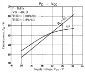
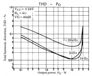
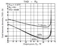
HTA-2000 power and distortion
Let's take a little more in-depth look at what this chip amp can do by looking at a couple of plots from the datasheet:
The first attachment shows a plot of the output power versus rail voltage. The second and third attachments show the THD for 8 ohm and 4 ohm loads for 20Hz, 1kHz, and 20k Hz.
So, what do these tell us?
With rail voltages around +/- 28V (8 ohm loads) and 24V (4 ohm loads) you can get the claimed 25W/ch and THD specified. Note that the THD spec is tied to the 20k Hz distortion level and there is less distortion at 1k Hz and below. This means that a bridged HTA-2000 operating into 8 ohms and restricted to low frequency (below 1k Hz) will provide good performance.
Looking at the Po vs Vcc plot shows that the 4141v IC can deliver quite a bit more output if the rail voltages are increased - over 50W into 8 ohms and to about 45W into 4 ohms. The limit for rail voltages for the 4141v is about +/- 40V and power dissipation increases as rail voltage increases. Although the area available for heat transfer is probably about 3-4 times as large as the Megawatt packaging of other chip amps, you will probably want to use a larger heat sink if you increase the rail voltages much above the amp's 24V/28V rails - at that rail voltage the small heatsink gets moderately warm.
So, given that you can separately supply the chip amp with AC to its power supply, you could squeeze a lot of performance out of this amplifier for little cost, provided you can find the appropriate transformer. A 25-0-25V should give you rail voltages around +/-35V, and about 50W into 8 ohms. This is similar to the LM3886, but with a bit higher distortion. A 42VCT transformer will give you the 25W/ch spec'd in the datasheet. Both of these are available out there for relatively low cost.
This is not cutting edge low distortion stuff, but it's great for cheap and fun DIY audio projects! Remember, this is a pretty quiet amp (low noise) and would be perfect for a pair of computer speakers or even a larger pair for a small room where huge wattage is not required.
-Charlie
Attachments
Last edited:
FYI, Apex Jr has 60 pcs left of the 42VCT toroidal transformers that work nicely with this amp:
http://www.diyaudio.com/forums/apex-jr/210561-42-vct-toroidal-transformers.html#post2981423
...and I am sure that he also has the OEM transformer that is meant for this amp in the first place (and he sells the amp boards, too!).
Give Steve some business!")
-Charlie
http://www.diyaudio.com/forums/apex-jr/210561-42-vct-toroidal-transformers.html#post2981423
...and I am sure that he also has the OEM transformer that is meant for this amp in the first place (and he sells the amp boards, too!).
Give Steve some business!
-Charlie
Another interesting option for these amps is to replace the chipamp with a pin-compatible but more powerful one from the same series. For instance, the STK4191V is rated at 50W+50W but seems much better suited for 4 ohms loads, can deliver much higher power, and be used with higher rail voltages. This would not only provide better 2 channel power (50+ watts is plenty of power for an active system) but using these in a bridged mode would allow for 100+ watts into 8 ohms for a woofer or subwoofer. I found some of the STK4191V on Ebay for about $5 each. My plan is to replace the STK4141V (that come with the amp) with the STK4191V, change out a couple of caps, create an off-board power supply and see how it goes.
I can envision a 3-way with the STK4191 bridged on the woofer, and the STK4141V for the mid and tweeter.
-Charlie
I can envision a 3-way with the STK4191 bridged on the woofer, and the STK4141V for the mid and tweeter.
-Charlie
I'm so glad that there is so much interest in this nice little amp board... that I have to post an update:
I am planning to put a pair to use soon, for the midrange and tweeter of a 3-way that I hope to be bringing to Burning Amp. Both drivers are 8 ohm, and I will use the 42VCT ApexJr toroids to power it, so I should get pretty good performance.
Did I mention that I love these little amp boards!
-Charlie
and where would this be superior in any ways to a pair of gainclones?
if you need a bigger traffo, a replacement heatsink, and so on.
why not justgrap a pair of these:
http://www.ti.com/lit/ds/symlink/lm4765.pdf
a proper traffo, and some proper opamps. say like tl84 or so.
edit, first was thinking it may be cheaper, but the cost differnce is not that big.
if you need a bigger traffo, a replacement heatsink, and so on.
why not justgrap a pair of these:
http://www.ti.com/lit/ds/symlink/lm4765.pdf
a proper traffo, and some proper opamps. say like tl84 or so.
edit, first was thinking it may be cheaper, but the cost differnce is not that big.
Last edited:
and where would this be superior in any ways to a pair of gainclones?
if you need a bigger traffo, a replacement heatsink, and so on.
why not justgrap a pair of these:
http://www.ti.com/lit/ds/symlink/lm4765.pdf
a proper traffo, and some proper opamps. say like tl84 or so.
edit, first was thinking it may be cheaper, but the cost differnce is not that big.
Well, you don't have to replace the heatsink. The PS is onboard - you only need a transformer. The footprint is small and the amp board is already built for you. If you use the amp plate mostly as is, you also get a power switch, power cord, fusing, etc. It's ready-to go. By bypassing the line level circuitry and feeding directly into the chip amps you get something that you could have up and running in a day and could use with an outboard crossover or one built into your PC. For instance I have a multi-output sound card, and I will probably use a pair of these to build powered computer speakers, using the soundcard to implement the crossover.
All of this translates into a package that is cheaper and easier than two gainclones.
-Charlie
Just posting a follow up in this thread. I recently replaced the STK4141V with the pin-compatible STK4191V, which has about twice the power output capability (and more) and is better suited for 4 ohm loads. This worked like a charm. Note that for both of these I removed and replaced the onboard PS with an off-board one. See this thread for details and THD measurements:
http://www.diyaudio.com/forums/pass-labs/220442-amplifier-testing-how-questions.html
After running the amp with the new STK4191V into a 4 ohms load it is surprising that the small heatsink is still pretty cool... The 4191V's are available on Ebay in lots of 10pcs or 20pcs. Great way to DIY a 2-channel 60+WPC amp!
-Charlie
- Status
- This old topic is closed. If you want to reopen this topic, contact a moderator using the "Report Post" button.
- Home
- Amplifiers
- Chip Amps
- Using the HTA-2000 2-ch amp for DIY