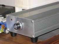
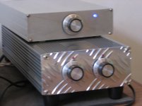
for the power supply i used a transformer salvaged from an old 'hifi' i put it in an old ups box with 20000uF capacitance, i got about 30 volts per rail unloaded. here's the case, it's a little rough, my first go please be kind") the small one on top is a lm1875 in an old external drive box.
the small one on top is a lm1875 in an old external drive box.
the small one on top is a lm1875 in an old external drive box.Attachments
I enjoy it! I like the " I did not buy it look", also. I like finding parts to use in builds also. Really like doing DIY projects and finding a use for electrical equipment that would otherwise be sent to landfills or waste. There is so much electrical equipment that needs to be put to use.
Enjoy your amps!!!
Enjoy your amps!!!
I'm not surprised that it's quiet, because you did everything right by twisting together all of the wire pairs, so they wouldn't act as antenna loops. Great work.
Also, I love that the local decoupling caps are so close to the chips. What values did you use, there?
How long are the power and ground wires from the chips to the PSU caps?
How did you route the grounding?
Did you run additional separate ground wires from the chip input ground reference points back to the PSU ground?
Where do the speaker ground returns connect?
I'm not surprised that it's quiet, because you did everything right by twisting together all of the wire pairs, so they wouldn't act as antenna loops. Great work.
Also, I love that the local decoupling caps are so close to the chips. What values did you use, there?
How long are the power and ground wires from the chips to the PSU caps?
How did you route the grounding?
Did you run additional separate ground wires from the chip input ground reference points back to the PSU ground?
Where do the speaker ground returns connect?
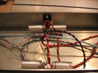
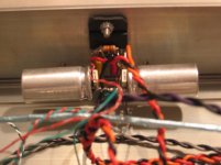
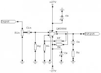
i knew about twisted pairs from a little pa experience, my thinking was that i could use smaller value 1500uF local decoupling capacitors of decent quality and then cheaper ones for bulk storage in the remote supply, the small film ones are 33nf no reason other than i had them. the power and ground wires are 350mm long, the speaker grounds connect directly to the ground plane where the local decoupling caps are, the input grounds are also connected there but with a longer line to lift the ground slightly. seems to work pretty well, i came to this arrangement by trying all different schemes, for me this one seemed to work well, less chance of loops i think. i'm not a electronics boffin, i figure stuff out with my hands. thank you for your feed back.
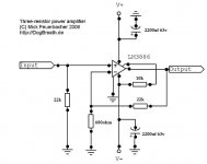
i based my schematic on Mick Feuerbacher's three resistor amp. there is no input capacitor nor is there any Ci on the feed back circuit, i am confident that my source has no dc on it's output. it has gain down to dc so if you try it please be careful and try it on old rubbish speakers first. when i powered it up for the first time i put 15ohm resistors on the power rails to limit the current in case of mistakes. i could swear electronics work on smoke, if it comes out they stop working!
Attachments
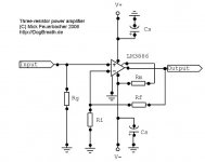
in relation to the preceeding schematic, Rg 22k, Rf 22k, Ri 680R, Rm 10k, Cs 2200uF 63v electrolitic bypassed with 100nF polyester. this will give you a gain of about 33 quite high but then you can drive it directly without a pre amp. for the power supply i used the basic power supply found in chip amp power supply a beginner's guide. hope you find this helpful.
in relation to the preceeding schematic, Rg 22k, Rf 22k, Ri 680R, Rm 10k, Cs 2200uF 63v electrolitic bypassed with 100nF polyester. this will give you a gain of about 33 quite high but then you can drive it directly without a pre amp. for the power supply i used the basic power supply found in chip amp power supply a beginner's guide. hope you find this helpful.
Thanks Wazzy. I will have to gather parts and build one. thanks.
Sure will - I have LM1875T chips on hand - how would i modify the circuit to accomodate these instead of 3886.openback, let us know how it goes.
Attachments
- Status
- This old topic is closed. If you want to reopen this topic, contact a moderator using the "Report Post" button.
- Home
- Amplifiers
- Chip Amps
- my lil p2p lm3886