I have been reading a lot on this forum about how to protect the speakers in case the output transistors failed. If this will happen the speakers will be destroyed due to the rails high voltages. So I decided to design a protection system that will protect the speakers from this to happen by using a microprocessor. Another thing that brought me the attention to design it was my LM3886 built. It is running at the max rails voltage of +/- 40 volts. If one of the LM3886 will fail my speakers will be destroyed.
There are some microprocessors that are too expensive for this project so I decided to use the new NANO series from Basic Micro. Their prices start from the 3 dollars to the $12.98. They are programming using the simple basics instructions and also have the floating point. The good advantage of using a microprocessor versus hardware wise is that using the microprocessor all the changes are done in the programming and not in the hardware. You do not have to unsolder and soldered to make the changes. If you wants to change the delay just change the instruction value for the delay. The best NANO for this application is the NANO 8. It is has 8 pins microprocessor with four I/O pins. Enough I/O pins for this application.
For more information for the NANO series check it in the Basic Micro web side.
To build this project I used the NANO 28 that it is a left over from another project. It is an over killed due to too many I/O pins that will not be uses. Right now everything it is running flawless in the testing/debugging mode with no problems. The microprocessor it is programmed to do the following sequencing of event.
Power up sequencing
1– Disable the output speaker relay.
2- Enable the mute (optional).
3- Delay 4 second before enable the speaker output relay to allowed the rail voltages to stabilized.
4- Monitor the speakers output voltages to be within limit (1.0 volts).
5- if voltage is within limit then close the output relay.
6- Delay for 4 seconds to allowed the relay de-bouncing.
7- Disable the mute circuit.
8 –Continuously monitoring the speaker output voltage to be constantly changing or the rails voltage it is not reach. In case of clipping the output relay will be disable.
If the reading is constantly the same for a period of time then immediately disable the output relay, enable the mute circuit and turn on the fault led light indicating the amplifier speaker outputs has a high output voltage and must be corrected.
There are some other extra that can be added but for now just the basics to see how it is work out.
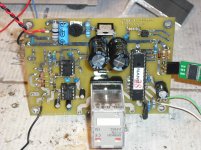
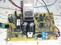
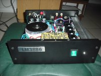
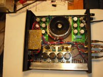
Right now I have one speaker protection system installed in my LM3886 amplifier built by myself. The LM3886 and the speaker protection printed circuit boards were fabricate by ExpressPCB using my printed board circuit layout design.
Attached are some pictures of the two boards and the amplifier. The relay board in the picture is an unfinished board waiting for a TL783 linear regulator to finish it. I will keep it as a spare.
There are some microprocessors that are too expensive for this project so I decided to use the new NANO series from Basic Micro. Their prices start from the 3 dollars to the $12.98. They are programming using the simple basics instructions and also have the floating point. The good advantage of using a microprocessor versus hardware wise is that using the microprocessor all the changes are done in the programming and not in the hardware. You do not have to unsolder and soldered to make the changes. If you wants to change the delay just change the instruction value for the delay. The best NANO for this application is the NANO 8. It is has 8 pins microprocessor with four I/O pins. Enough I/O pins for this application.
For more information for the NANO series check it in the Basic Micro web side.
To build this project I used the NANO 28 that it is a left over from another project. It is an over killed due to too many I/O pins that will not be uses. Right now everything it is running flawless in the testing/debugging mode with no problems. The microprocessor it is programmed to do the following sequencing of event.
Power up sequencing
1– Disable the output speaker relay.
2- Enable the mute (optional).
3- Delay 4 second before enable the speaker output relay to allowed the rail voltages to stabilized.
4- Monitor the speakers output voltages to be within limit (1.0 volts).
5- if voltage is within limit then close the output relay.
6- Delay for 4 seconds to allowed the relay de-bouncing.
7- Disable the mute circuit.
8 –Continuously monitoring the speaker output voltage to be constantly changing or the rails voltage it is not reach. In case of clipping the output relay will be disable.
If the reading is constantly the same for a period of time then immediately disable the output relay, enable the mute circuit and turn on the fault led light indicating the amplifier speaker outputs has a high output voltage and must be corrected.
There are some other extra that can be added but for now just the basics to see how it is work out.
Right now I have one speaker protection system installed in my LM3886 amplifier built by myself. The LM3886 and the speaker protection printed circuit boards were fabricate by ExpressPCB using my printed board circuit layout design.
Attached are some pictures of the two boards and the amplifier. The relay board in the picture is an unfinished board waiting for a TL783 linear regulator to finish it. I will keep it as a spare.
Attachments
It is very important that the cpu can drive the relays to off fast enought. You might considder mosfet "relays".
One way to see if things goes very wrong is to know the max current and have a adc meassure output from an Allegro hall element. To meassure dc in the ac signal is important, but might difficult in software of a small chip.
Nevertheless, You do need several adc inputs per amp.
Another way to do the protection, is the old "analog" way, but having the outputs, from these parts trigge the cpu, and let that control the relays, fanspeed and so on.
The nano chip You are talking about might not be overkill, as You might wanna on several faults seperatly, to do reporting for a pc or equal") .
.
One way to see if things goes very wrong is to know the max current and have a adc meassure output from an Allegro hall element. To meassure dc in the ac signal is important, but might difficult in software of a small chip.
Nevertheless, You do need several adc inputs per amp.
Another way to do the protection, is the old "analog" way, but having the outputs, from these parts trigge the cpu, and let that control the relays, fanspeed and so on.
The nano chip You are talking about might not be overkill, as You might wanna on several faults seperatly, to do reporting for a pc or equal
.Hi,
The idea seems fair enough but is probably total overkill for a chip amp,
but probably with a bit more work, monitoring output current, it could
possibly replace the SOA protection of a discrete power amplifier.
I find it hard to believe a chip amp is likely to fail in the manner described.
rgds, sreten.
I said is an over kill because I was looking for a minimum parts to keep cost down. Right now I am using only two analog inputs and two outputs. One for the relay, one for the mute and two to read the speakers output.This is only for a test to proved that it is possible to used a microprocessor for this application. I am using a SSR for the mute. I may consider your suggestion. using mosfets transistors instead the relay. I will try to research it. It will be easy to implement just built something that plug in the relay socket.
Thank you. I am thinking also to implement to read the heat sink temperature and disable the speaker outputs.
Thank you. I am thinking also to implement to read the heat sink temperature and disable the speaker outputs.
Updated program to include rails voltage drop
Added in the program to check for rails voltage drop to disable speaker output relay
Power up sequencing
1– Disable the output speaker relay.
2- Enable the mute (optional).
3- Delay 4 second before enable the speaker output relay to allowed the rail voltages to stabilized.
4- Monitor the speakers output voltages to be within limit (1.0 volts).
5- if voltage is within limit then close the output relay.
6- Delay for 4 seconds to allowed the relay de-bouncing.
7- Disable the mute circuit.
8 –Continuously monitoring the speaker output voltage to be constantly changing or the rails voltage it is not reach. In case of clipping the output relay will be disable.
9-Check rails voltage drop to disable speaker output relay - gathered it from Puppet threads "Amplifier pwr down "thump" issue" <<<<< Added
I'm developing a "micro" controlled amplifier (based on the P101 of Rod Elliott) too.
The micro (ATMega16) will drive a small 320x240 color LCD but also will control:
- +/- 56V power supply on/off
- soft-start for the (above) PSU with a protection if the bypass relay fails and the "inrush" current limiter resistors get too hot
- PSU overload protection (using 2 ADCs the rail voltages are monitored and if their value get lower than 45V, the micro turns off the PSU)
- DC speaker protection (using 2 ADCs, one for channel)
- output transistor thermal protection (using two simple thermal switches, if one of them closes the micro turns off the PSU)
The LCD will show:
- the current value of the rails voltage
- the active protection
- the output power (RMS)
The circuit (and the method) to measure the output power is still under study...I have two Allegro ACS712-30 (30 Ampere AC/DC) that I could use to measure the current absorbed by the amp, then detracting the quiescent current and multiplying it for the current rail voltage I could calculate (with approximation) the power supplied to the loudspeaker.
Any other idea to measure the output voltage without using a True-RMS to DC converter?
Hi,
My design almost it is doing the same thing that your are proposing to use in your design. For the temperature you can use the LM35. The temperature output it is in millivolts proportional to the temperature. For the current I would use a low value precision resistor and read the voltage at both end. Then calculate the current using the ohms law. Since the output it is changing constantly I would use small filter to smooth it. Right now all the values I am reading are dumping to the computer. I have an output to the display no using it now. I am using a led to indicate a fault. My prototype it is working flawless in the power up / down. I simulate a high speaker reading and the relay turn off immediately.
Belief me it is so simple to do it we a microprocessor. All the changes are done software wise and no components to change. One thing that you most be sure it is to have all the inputs that you will need and add some space in the board just in case you need to add some extra components.
Right now I am working in a solid state relay to replace the speaker output relay like somebody suggested.
Right now I am working in a solid state relay to replace the speaker output relay like somebody suggested.
I'm sure you must have seen this,
http://www.diyaudio.com/forums/solid-state/191449-output-relays.html
I built some as a direct replacement for standard relays,
http://www.diyaudio.com/forums/solid-state/191449-output-relays-13.html#post2659578
http://www.diyaudio.com/forums/solid-state/191449-output-relays-14.html#post2660474
DC protection is an interesting subject. Does anyone ever test it though for real such as sticking a screwdriver across an output transistor
You could always use say a 1 watt or whatever resistor as a dummy load and see what survives.I've never seen a chip amp fail putting out DC. We have some 30k+ units of TDA7294/TDA7292-based products out in the field but we have had zero reports about drivers been taken out by DC so far.
I don't have that vast experience with the LMs but I think they're safe, too.
I see no neccessity for a uC here, just use appropriate circuits for mute/standby pins sensing startup/loss of AC (and temperature, maybe)
I don't have that vast experience with the LMs but I think they're safe, too.
I see no neccessity for a uC here, just use appropriate circuits for mute/standby pins sensing startup/loss of AC (and temperature, maybe)
My point it is that by using a micro to design an electronic design it is more flexible that using electronics components. Changes also are more easy to do software wise than making hardware changes. Still an LM3886 can fail it is used in too hard environments. Like to much voltages, bad power supply etc, etc. Maybe I used the wrong example but still the micro can be use to protect any direct amplifier that the output it is capable of destroy the speakers. Almost today all electronics device have a micro to control it.
I know what you meant, I've been using micros for almost 5 years now, I've built a lot of "intelligent" boards for my own use.
I thought to use the LM35 but I've used all the 8 ADCs that the ATMega16 has so I'm going to use thermal switches instead.
Check out the DS18B20. No need for an ADC, and quite easy
to interface.
I like the idea. But how do you know that your step 8 will always work, as it is now programmed?
Anyway, I would be interested in how and why you programmed it to check to see if the "speaker output is constantly changing". The fault-detection algorithm would be a critical part to get right, since it triggers the actual DC protection, correct?
What if the voltage was a DC fault, somewhat near a rail voltage, but constantly changing by enough that your algorithm didn't flag it as a problem? i.e. The exact details of how you detect faults are the most important part (but you have not discussed those details).
Would your software detect a very large DC offset (but not to the rail) that still had noise or a small music signal on top of it?
It seems like you might want to do some sort of averaging (but still do it "fast-enough"), in order to detect DC.
What about a large DC-offset-fault-condition signal that was changing with a few volts p-p (maybe the volume knob was turned fairly low) but the average was half of the rail voltage, for example?
You would really need to figure out, "What are all of the situations that need to be detected, to prevent damage to a speaker?". And then figure out "What is needed to detect all of those situations?". And then you might want to try to minimize the necessary detection measurements and the algorithm size and execution time. So you also need to know, "How fast does it really need to work?".
Since you have everything else you need already in place, you really should try to make sure that the programming is taking the fullest advantage of the situation.
I'm also interested in how you are measuring, in the analog domain. For example, are you using instrumentation amplifier types of circuits (or maybe even instrumentation amp chips, e.g. AD620) that will give you the voltage across a small resistor, in order to measure current? A one-opamp differential amplifier would work, too, but would probably not give such a high input impedance. Just curious as to where and how you are measuring.
You might be able to do most calculations (e.g. RMS) in software. But if you need them, there are relatively-cheap RMS-to-DC converter chips, e.g. LTC1968 at linear.com, and relatively-cheap analog multiplier/divider chips, e.g. AD633 at analog.com.
I'm sorry that my thoughts were not very well organized.
Cheers,
Tom
Last edited:
To gootee
In the way I check the output voltages it is by reading the output voltages and at the end of all check it is saved. Then in the next reading both reading are compare and if they matched a counter it is incremented. When the counter reached a predetermined setting the relay it is immediately disable. Right now if the counter reached 7 count the output relay it is disable. The seven was found by playing different type of music until the relay was not disable. But at the same time also the output voltage it is check to see it they are within predetermined limits. At the start up the voltages are check to be less than .5 volts. If not the relay it is not close.
The way I am doing the checking it is not too fancy but it worked flawless.
Right now I working to read the output current as few of the members recommended it. I think by checking the current will be enough to determine if the relay will be close or stay open.
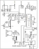
In the way I am planning to do it is by connecting the amplifier output to a solid state relay to the speaker then the speaker ground through a 1 ohm resistor to ground. By checking the voltage at the resistor I can determined the current. The problem I have is what to do next. Do I calculate the current base on the amplifier max. watts to disable the relay or determine by the max. current that the output transistors can handle? what to do ??????. This is the question.
Attached It is the schematic I am using right now.
In the way I check the output voltages it is by reading the output voltages and at the end of all check it is saved. Then in the next reading both reading are compare and if they matched a counter it is incremented. When the counter reached a predetermined setting the relay it is immediately disable. Right now if the counter reached 7 count the output relay it is disable. The seven was found by playing different type of music until the relay was not disable. But at the same time also the output voltage it is check to see it they are within predetermined limits. At the start up the voltages are check to be less than .5 volts. If not the relay it is not close.
The way I am doing the checking it is not too fancy but it worked flawless.
Right now I working to read the output current as few of the members recommended it. I think by checking the current will be enough to determine if the relay will be close or stay open.
In the way I am planning to do it is by connecting the amplifier output to a solid state relay to the speaker then the speaker ground through a 1 ohm resistor to ground. By checking the voltage at the resistor I can determined the current. The problem I have is what to do next. Do I calculate the current base on the amplifier max. watts to disable the relay or determine by the max. current that the output transistors can handle? what to do ??????. This is the question.
Attached It is the schematic I am using right now.
Attachments
- Status
- This old topic is closed. If you want to reopen this topic, contact a moderator using the "Report Post" button.
- Home
- Amplifiers
- Chip Amps
- Protecting the speaker output using a microprocessor