As I look at the application sheet AN-1192 I find that
in parallel of two LM3886 the feedback resistors are 20K,
on the other hand the same is about 47 and 51K in the
bridge of two LM3886. Why is this? My circuit is attached
in the parallel version. I thought I just have to exchange
the Amp input and the output of the AD8620 connection
to one of the LM3886. Do I have to change the feedback
resistors also.
Please let me know.
Thanks
Roushon.
Thanks Roushon
")
I don't recommend to build an audio amplifier with two LM3886 in parallel. There are a lot of factors that must follow to obtain an appropriate quality level. Solution is used if you wish to use LM3886 the very low impedance (less than 4 ohms). Distortions obtained are quite high and the circuit implementation is even more difficult make as we are forced to find two LM3886 as more identical.I requested for a suggestion in my old following thread. But it got the
wrong thread name. That is why started this new thread. The request is
here:
http://www.diyaudio.com/forums/chip...ted-lm3886-buffer-dc-servo-7.html#post2940248
For a 8Ohm speaker which sounds better: parallel or bridge of two LM3886.
Thanks
Roushon
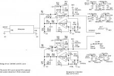
Modified circuit
More trouble than I thought. Have to cut several tracks
and need one resistor and a capacitor more for the
non-inverted amp. The circuit is attached.
Please have a look and tell me if any correction is needed
before I start cutting tracks. It will be cumbersome. The
buffer may or may not be there at the input.The attenuator
has input and output impedances both 10K.
N.B. Note that the pin numbering of the AD8610 is not correct.
It was AD8620, I changed it but forgot to the change the pin nos.
Thanks and regards
Roushon
Attachments
Last edited:
and repeat the additions for the other half of the signal.
what do you mean "10k attenuator"?
The attenuator circuit is attached. I do not understand
the first line. Sorry!
Regards
Roushon
Attachments
The attenuator shown does not have a 10k output impedance.
To give accurate dB attenuations for each step and combination of steps the attenuator needs to see a load impedance of 10k. That is very different.
With all the relays pulled in to bypass all the series resistors, the output will see the Source Impedance.
Let the last (rightmost relay contact) trip over to the 6r31 connected to Signal Ground.
The load now sees 6r31//[10k+Rs]. This is very definitely not =10k.
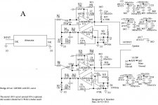
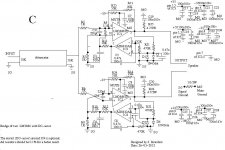
You have added 0u47F & 470k to the lower amplifier DC servo circuit.
The upper amplifier does not show these additions. Why?
You have shown the extra 0u47F connected to -IN PIN. I think it should be connected to the other side of the lower 470k, i.e. to Signal Ground.
Note that the whole of the lower DC servo circuit is in parallel to R14.
The DC servo circuit is an alternative route for the feedback signal.
That must be repeated for the upper amplifier.
Last edited:
Thanks Andrew for the clarification.
I am following (may be blindly) National Application notes AN-1192 for the amp.
1. in the lower dc-servo the 0.47 will be connected to SG, this was a mistake.
2. should I repeat the same for the dc-servo for the non-inverted amp too?
that is 0.47 between -IN of AD8610 to SG and 470K between +IN and SG (instead of directly to SG). This is not done in AN-1192.
Regards
Roushon.
Just looked at the application notes again. It is clearly mentioned (page 13, 3rd
para) that the non-inverting type servo can be used for the inverting amp
(connected parallel to Rf), in that case we will need the extra 0.47 and 470K.
But this extra RC can be avoided if an inverting dc-servo is used with the
inverting amp.
I hope it is OK.
Regards
Roushon
para) that the non-inverting type servo can be used for the inverting amp
(connected parallel to Rf), in that case we will need the extra 0.47 and 470K.
But this extra RC can be avoided if an inverting dc-servo is used with the
inverting amp.
I hope it is OK.
Regards
Roushon
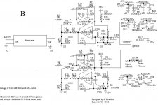
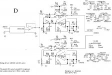
You appear to have adopted non-inverting servos and taken both to the -IN.
I am not sure, but it looks right. Why is R9><R10?
The attenuator is still loaded with 1k0//Rin(of the non-inverting amplifier).
The inverting amplifier gain will still change with changes in the attenuator's output impedance.
I am not sure, but it looks right. Why is R9><R10?
The attenuator is still loaded with 1k0//Rin(of the non-inverting amplifier).
The inverting amplifier gain will still change with changes in the attenuator's output impedance.
Another mistake in typing. In the board both R9 and R10 are 5.1K.
May be I will place the buffer in between the attenuator and the amp.
Actually the amp at present (parallel of two inverted) is attached
with the attenuator directly and working OK. Not experienced enough so
my understanding of its performance may be not accurate.
Thanks
Roushon
May be I will place the buffer in between the attenuator and the amp.
Actually the amp at present (parallel of two inverted) is attached
with the attenuator directly and working OK. Not experienced enough so
my understanding of its performance may be not accurate.
Thanks
Roushon
In any case the distortion will be multiplied: you have 2 amps generating noise and distortion compared to only one.
I know it isn't intuitively obvious but the signal to noise ratio will IMPROVE. The noise is random and will add as the square root of 2 but the signal is not random and will add linearly so the RATIO of signal to noise will improve and NOT get worse. I first saw this an an Ampex 2" VTR where they run 4 amplifiers in parallel to get even a little better S/N ratio improvement in the RF amplifier front end - actually 4 amps for each of the 4 channels.
G²
That is a good news for me. I will try to improve my existing parallel amp
instead of trying to convert it into a bridge which is giving me more pain
than I thought.
Roushon
- Status
- This old topic is closed. If you want to reopen this topic, contact a moderator using the "Report Post" button.
- Home
- Amplifiers
- Chip Amps
- Does bridge of two LM3886 sound better?