Maybe you should try posting this kinda stuff in the SMPSU section...I dun really like to deal with them...and I haven built or tried one yet...so before I continue...get your PSU up and running good first...I also see that you like to post in the SwitchMode Group...(yahoo)...I currently have an account there...perhaps you can post and get answers there..while I chip in to help a bit...most importantly ...get the PSU section up and running...an Amp without a PSU is like a car without an engine...
Right.an Amp without a PSU is like a car without an engine...
Thanx for ur help anyway!
I would think ur amp is ok...but the PSU section is broken from the pics you posted..perhaps you can post some pictures of ur SMPSU...or izzit on another thread?? Maybe you can get a cheap0 4A 2x 30VAC Trafo...doesn't have to be really good...rig up a simple PSU...with some caps and a rectifier...then test away...once the power amp section is ok...proceed to fixing ur SMPSU...I think the schematic on Rod's site..at
http://sound.westhost.com/project89.htm
is really good...I haven tried it personally...but I do know a few people here have...so give it a shot...you might want to use parts from ur previous SMPSU...
http://sound.westhost.com/project89.htm
is really good...I haven tried it personally...but I do know a few people here have...so give it a shot...you might want to use parts from ur previous SMPSU...
http://www.diyaudio.com/forums/showthread.php?s=&postid=242581#post242577or izzit on another thread??
If you notice the final part is exactly the same.. Except for the sg3525 that my supplier finished... Well he have only one but i burned it so i've to use the sg3524.. not the best choice i know!think the schematic on Rod's site
I guess so...and the SG3525 can be "purchased" for free...check it out at
http://www.onsemi.com/site/products/summary/0,4450,SG3525A,00.html
Click on the samples button...fill in the necessary details registeration form etc...you get 20 for free...hehehe...you are probably wondering why I didn't tell you earlier...you do have to wait for the chip to arrive at your doorstep though...
Originally posted by MaXiZ
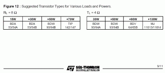
At http://www.ampslab.com/ia502schema.htm is reported to use the 142/147 and u say to don't use them.. why?
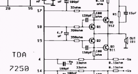
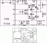
Look closely at the output section. Your schematic does not drive power darlingtons.
And i saw "input sensitivity 1v".. This mean that if my car stereo give and output of 30mV@360mA i can't hear nothing. Right?
This chip is not meant for cars.
SO i need a preamp right?This chip is not meant for cars.
Originally posted by li_gangyi
Read the posts carefully...
It would be wise of you to read my post carefully too.
Would you explain to me where the power darlingtons are?
Attachments
Read again...it's at Q1 and Q2...probably he used the wrong symbol...that's why you got a bit messed up..looks like a little argument btw me and you here...hehe...2 Singaporeans...As Q1 and Q2 i've used TIP142/147 that should be enough to have 70W+
He could have been aiming for more output current or something...that's why he place another pair there...or maybe he doesn't know what he is doing...no matter what..I still think his SMPSU has a problem...what do you think?? And yes...I do have a lot to learn about amps...
Anyways...the TIP142s and TIP147s are reccommended by the manufacturer...I have posted a short segment of the PDF (datasheet) here...hope you can download the datasheet and look through it before trying to post again..seems like wrong information might mess up this guy...hehehe
Attachments
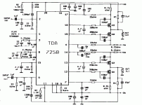
2 ways to use TDA7250
You will find that on page 6 of the application notes is "Figure 1 - Application Circuit with Power Darlingtons" whereas on page 9 is "Application Circuit using Power Transistors".
Please note that these 2 circuits are not the same.
Page 6 uses Darlington Outputs (TIP147/142) for Q1, Q2, Q3, Q4.
Page 9 circuit use drivers Q1, Q2 to drive output transistors BD912/911 which are configured as a Sziklai Compound Pair.
By the way...you should be using a more powerful...higher current power supply input for your SMPSU...1.5A is NOT enough for it...due to the fact that it is stepped up...it would drop to under an amp...and also sorry to MCP for not being really clear...and yeah...the TIPs should be at Q1, Q2, Q3 and Q4...
- Status
- This old topic is closed. If you want to reopen this topic, contact a moderator using the "Report Post" button.
- Home
- Amplifiers
- Chip Amps
- First attempt to build a Power amp!


