Hi:
I am new to this forums here at DIYAUDIO, I found this site searching help for some issues I was having with speaker's crossovers.
Now, I have learn a lot from you all, it's been really nice, and this have encouraged me to experiment and learn more.
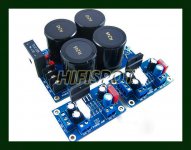
I recently purchased a XY LM3886 amplifier kit at eBay. It is composed of 2 amplifier boards and a regulated power supply unit. I have attached a picture of the actual kit I bought. I have not received it yet, but I want to know your opinions about this kit, and if there is anything to improve it.
I also purchased a ALPS potentiometer for it, I have seen that they also sell "speaker protection boards", do I need one of those?.
I also know I will need a transformer, I was thinking about a toroidal from Antek, the AS4222 22V 400VA, is this OK for this setup?.
Thank you very much.
I am new to this forums here at DIYAUDIO, I found this site searching help for some issues I was having with speaker's crossovers.
Now, I have learn a lot from you all, it's been really nice, and this have encouraged me to experiment and learn more.
I recently purchased a XY LM3886 amplifier kit at eBay. It is composed of 2 amplifier boards and a regulated power supply unit. I have attached a picture of the actual kit I bought. I have not received it yet, but I want to know your opinions about this kit, and if there is anything to improve it.
I also purchased a ALPS potentiometer for it, I have seen that they also sell "speaker protection boards", do I need one of those?.
I also know I will need a transformer, I was thinking about a toroidal from Antek, the AS4222 22V 400VA, is this OK for this setup?.
Thank you very much.
Attachments
Take a look at this thread on the same amp --->> http://www.diyaudio.com/forums/chip-amps/206658-3886-ebay-kit-build.html
Can I replace the Wima input capacitors with Audiophiler MKP 4.7uf 400V axial capacitors?. If not, what would be the best replacement?.
Do I need to get the "speaker protection board"?.
Thank you.
If you can fit them in there then go for it ..... i put in some huge 4.7uF mylar caps in my boards (got the boards for $2.50 each on e-bay) and was able to get them to fit but it is a really tight squeeze ......
As for the speaker protection I guess it is optional ......
Cheers
have you got pics of the top and bottom of the blank PCB?
Many of these PCBs have commoned the Signal Ground with the Power Ground.
In a monoblock amplifier, you need to move the Main Audio Ground onto the PCB.
In a dual mono amplifier and in a stereo amplifier, you must cut the Signal Ground connection to the Power Ground. Then select an off board location for a single Main Audio Ground shared between the two channels.
If you have bought a parts kit from China, or nearby, then check that all the components are what is written on the labeling. You may have to discard many of the supplied Chinese components.
and 118posts later he has successfully built his amplifier. All because there is no support from the retailer....look at this thread on the same amp --->> http://www.diyaudio.com/forums/chip-amps/206658-3886-ebay-kit-build.html
What if the Forum was not here?
Hi:
I wasn't able to post because my ISP was having problems.
Ok, since the speaker protection board seems to be a good thing to use, could you please tell me how to power it, in the specifications posted by the seller he says that this requires 12-16V to operate, and that an additional power supply is recommended. I ordered a Antek AS3428, 28V 300VA that has dual 28V outputs and dual 15V outputs. Would this do the job?.
he says that this requires 12-16V to operate, and that an additional power supply is recommended. I ordered a Antek AS3428, 28V 300VA that has dual 28V outputs and dual 15V outputs. Would this do the job?.
Since he says that it need 12-16 VAC one of the 15 V outputs will do.
And that power supply isn"t regulated , it is just a regular unregulated PSU ......
Uh, most amplifier PSUs are non-regulated. The chip amp IC has enough ripple rejection to not require any regulation like a line level circuit.
-Charlie
Thank you, pacificblue.
I have one more question, there is an input selector board at the auction site, it has 4 inputs, 1 output, and the seller says that it requires anywhere from 11 to 22 Volts of AC. This may sound like a stupid question, but the truth is I don't know much about this:
Can I use the additional 15V output from the toroidal to power up this board too?.
The seller also mentions that this board has a "regulator output of 12V DC 1A", what is that?.
Following your advice, I just ordered the speaker protection board.
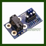
I have attached a picture of the input selector board.
Thank you very much once again.
I have one more question, there is an input selector board at the auction site, it has 4 inputs, 1 output, and the seller says that it requires anywhere from 11 to 22 Volts of AC. This may sound like a stupid question, but the truth is I don't know much about this:
Can I use the additional 15V output from the toroidal to power up this board too?.
The seller also mentions that this board has a "regulator output of 12V DC 1A", what is that?.
Following your advice, I just ordered the speaker protection board.
I have attached a picture of the input selector board.
Thank you very much once again.
Attachments
post15 pic.
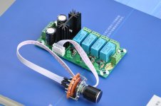
I can see 4 relays with 4 transistors and 4 diodes.
It appears that the inputs are relay switched using transistors as the trigger.
That an LED lights to show which is selected.
I can't see what is attached to the heatsink, but I will guess it is a 12Vdc IC regulator to suit 12V relays.
Yes you can use a single 15Vac supply. It is between 11Vac and 22Vac.
The 11Vac lower limit is a clue that confirms the 12Vdc regulator.
Check the trigger circuit and/or install information.
The transistors will need a low current low voltage trigger signal. This can be provided by a rotary switch, or other. But you must follow the instruction on voltage and current (source impedance) to prevent damaging the transistors.
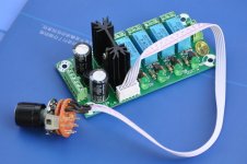
Input board pictures.
Andrew:
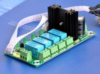
I am posting 2 more pictures plus the diagram for this input board.
Here, the specifications as posted by the seller:
Audio input selector module board, with 12V DC voltage regulator.
This item has been assembled, and electrical test passed.
4 Dual channel input, 1 dual channel output.
Led indicator for each relay channel.
Power Supply: 11 to 22V AC.
or 15 to 32V DC.
Regulator output: 12V DC / 1 Amp.
High quantity terminal block, easy connection wire.
FR-4 Fiber glass PCB ( Double Layer ).
Japan TAKAMISAWA signal relays.
Rotary switch wire length 300 mm (11.8 inch).PCB thickness: 1.6mm (0.063 inch).
Size: 100mm(L) x 50mm(W) x 38mm(H), (3.94 x 1.97 x 1.5 inch).
Andrew:
I am posting 2 more pictures plus the diagram for this input board.
Here, the specifications as posted by the seller:
Audio input selector module board, with 12V DC voltage regulator.
This item has been assembled, and electrical test passed.
4 Dual channel input, 1 dual channel output.
Led indicator for each relay channel.
Power Supply: 11 to 22V AC.
or 15 to 32V DC.
Regulator output: 12V DC / 1 Amp.
High quantity terminal block, easy connection wire.
FR-4 Fiber glass PCB ( Double Layer ).
Japan TAKAMISAWA signal relays.
Rotary switch wire length 300 mm (11.8 inch).PCB thickness: 1.6mm (0.063 inch).
Size: 100mm(L) x 50mm(W) x 38mm(H), (3.94 x 1.97 x 1.5 inch).
Attachments
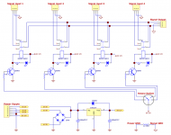
The trigger voltage and current are already defined by the switch circuit.
The current is ~ 12Vdc - transistor Vbe / 1k5 or ~7 to 8mA. This needs to be ~10% of the relay coil (+LED bypass) current to ensure the transistors are saturated and remain cool. The relay current is likely to be ~40mA. No problems.
The LEDs may run a bit bright. 12V-1.8Vled / 1k0 ~10mA.
Most LED indicators running at 10mA will be too bright in domestic operation. Easy to solve. Change the resistors from 1k0 to 4k7. If too dim then add a parallel resistor until you achieve desired brightness.
Thank you, Andrew.
I can then use this board in my project, I'll use one output of 15V from the transformer to power up the speaker protection board, then the other 15V to power this input selector board, and the only problem I'll be dealing with is the excess of brightness in the LED's which can be corrected replacing them with 4K7, correct?.
I can then use this board in my project, I'll use one output of 15V from the transformer to power up the speaker protection board, then the other 15V to power this input selector board, and the only problem I'll be dealing with is the excess of brightness in the LED's which can be corrected replacing them with 4K7, correct?.
- Home
- Amplifiers
- Chip Amps
- Bought a XY LM3886 Kit.