Hi Andrew:
I'm trying your formula, with C4, C5, R5, R6 and R4 as locations in the XY PCB, I'm using 2.2uF as reference value for C5:
C4 >= C5 * Sqrt(2) * [R5+R6] / R4
C4>= 2.2uF x 1.48323969 x [23000]/680=110.37
Now, when using a reference value of 4.7uF for C5:
C4>= 4.7 x 2.16794833 x [23000]/680=344.64
And using 1uF:
C4>=1.0 x 1.0 x [23000]/680= 33.82
According to this, if one is using 22K Ohm for R5, 1K Ohm for R6, 680 Ohm for R4, then C4 should be 100uF if using a 2.2uF in C5, 330uF if using a 4.7uF in C5 and 33uF if using 1uF in C5. Is this correct?. If that is the case, then I should use the 100uF in C4 instead of the 220uF you recommended.
Aguilabrava,
I have bought and sold several items through the use of local purchase and shipping internationally via simple mail like USPS. I one case the total service and shipping totaled close to $70 for $8 of parts. The package shipped to Italy for about $4.50.
So look for a friendly European DIYer")
I have bought and sold several items through the use of local purchase and shipping internationally via simple mail like USPS. I one case the total service and shipping totaled close to $70 for $8 of parts. The package shipped to Italy for about $4.50.
So look for a friendly European DIYer
Hi Andrew:
I'm trying your formula, with C4, C5, R5, R6 and R4 as locations in the XY PCB, I'm using 2.2uF as reference value for C5:
C4 >= C5 * Sqrt(2) * [R5+R6] / R4
C4>= 2.2uF x 1.48323969 x [23000]/680=110.37
Now, when using a reference value of 4.7uF for C5:
C4>= 4.7 x 2.16794833 x [23000]/680=344.64
And using 1uF:
C4>=1.0 x 1.0 x [23000]/680= 33.82
According to this, if one is using 22K Ohm for R5, 1K Ohm for R6, 680 Ohm for R4, then C4 should be 100uF if using a 2.2uF in C5, 330uF if using a 4.7uF in C5 and 33uF if using 1uF in C5. Is this correct?. If that is the case, then I should use the 100uF in C4 instead of the 220uF you recommended.
are your fingers faulty or is it the calculator/slide rule that is faulty?
sqrt(2) ~ 1.414
=105uF use, 120uF or 150uFC4>= 2.2uF x 1.48323969 x [23000]/680=110.37
4.7*1.414*23000/680=220uF, use 220uF or 330uFC4>= 4.7 x 2.16794833 x [23000]/680=344.64
1uF*1.414*23000/680 = 48uF, use 47uF or 100uF.C4>=1.0 x 1.0 x [23000]/680= 33.82
But all these DC blocking caps result in different bass response.
First has 23k & 2.2uF, second has 23k & 4.7uF, third has 23k & 1uF.
I couldn't compare these different options because each have a different filtering frequency.
BTW,
it's not my formula. I pinched from others before me, I just keep repeating the advice because I found it worked. It removed the sound effect from the NFB cap. Whereas using a too small NFB cap and increasing the input cap to restore the frequency response to where you want it, does make the sound output more susceptible to what type of capacitor is used in the NFB. Make it big enough and you can't hear any distortion due to that capacitor.
Last edited:
They have to be connected somewhere and those designers chose to do it on the board. You will have to ask them personally why they chose that location. The most likely reason is that it was the easiest solution.Why these three designers have grounds connected?
How good do they sound?Why they sound so good?
The connection to PE is for safety.Is this grounding issue just for safety or also to improve sound?
The connection from line level ground to output and power ground can have an impact on the sound quality. If the ground layout is bad, you get hum from an unregulated supply or cheeping noises if you use an SMPS.
Hey, Pacificblue:
I'm happy you are finally back...!
What Pemo is referring to is that the guys here, including himself, that have not separated the input signal ground from the power ground cutting the bridges in the back of the PCB don't have any hum at all, their amps are totally silent.
From your answer, I understand that this is just a safety related issue, so leaving those grounds together would reduce the possibility of getting hum, but would make the amp "not as safe"???
Me, too. One of my colleagues became ill and I had to take over his duties, so I am quite busy now and don't have much time left to spend with the Forum. The poor guy will probably be down for several months to go and there is no replacement in sight.I'm happy you are finally back...!
It depends on the overall layout whether you need to cut or not. If you have a central star-ground in a multi-channel amp, you may get hum, and then you will be obliged to cut those traces. You may as well be lucky, have a central star-ground and get no hum. Since there are infinite possibilities to lay your amp out, you just have to test it to find out. Some people skip the test and cut the traces just to be on the safe side.What Pemo is referring to is that the guys here, including himself, that have not separated the input signal ground from the power ground cutting the bridges in the back of the PCB don't have any hum at all, their amps are totally silent.
Andrew answered this already.From your answer, I understand that this is just a safety related issue, so leaving those grounds together would reduce the possibility of getting hum, but would make the amp "not as safe"???
Let me add that you are obliged to connect the audio ground to PE as soon as the voltage at the speaker terminals can become greater than or equal to 25 VAC or 60 VDC. The only way around this is to create a double-insulated connection from the amp to the speaker, e.g. by means of Speakon connectors on both sides of the speaker cable.
Below those voltages you are not obliged to connect PE to ground, but it is good to do it nevertheless. That way you get used to it and are less likely to forget it when the connection is necessary.
Friends, I have read the entire article regarding the amplifier "Aguilabrava". From what I've seen is a hipanoparlante like me. I congratulate you on the improvements made to the XY LM3886.
I have bought the same kit on ebay and I have replaced the electronics of these amplifiers poer Technics, Aiwa transformer with toriodal of 30 0 30 c and Rod Elliott preamps and phono line. tuner circuit is a Philips PM-FM. tuner.
Result: sound spectacular (with B & W DM602). show a photo. Greetings Jose.
An externally hosted image should be here but it was not working when we last tested it.
An externally hosted image should be here but it was not working when we last tested it.
An externally hosted image should be here but it was not working when we last tested it.
An externally hosted image should be here but it was not working when we last tested it.
Last edited:
Thanks Agui for your post. It help me to figure out my schematic for my XY pcb with LM3876.
It's a little bit different from you but it's also a three amp desing for active xover.
It's a little bit different from you but it's also a three amp desing for active xover.
An externally hosted image should be here but it was not working when we last tested it.
Here is the picture. Sorry.
Hi Johnny52
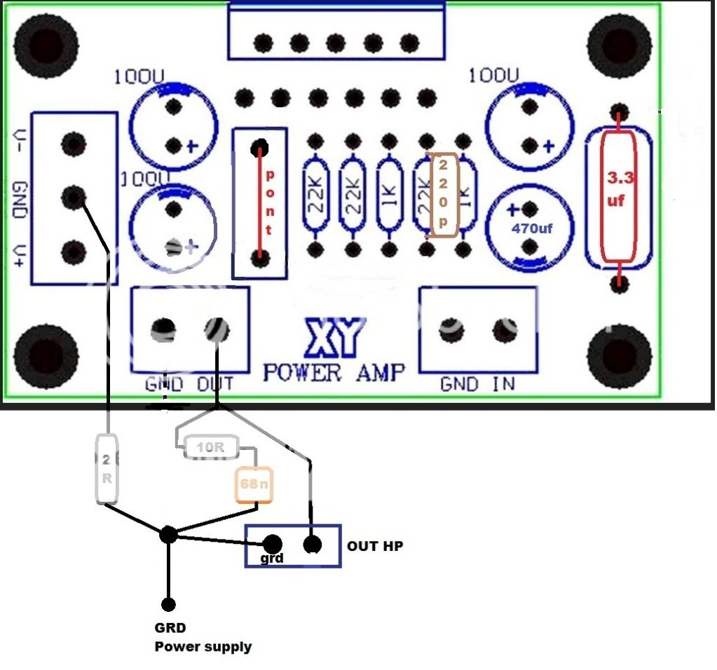
Your choice of implementation works (as in mine it does) but to be clear the best option is probably to cut the GND to really isolate the input/Feedback GND from the rest of the GND trace as pointed out earlier in the thread. Thus, this is the preferred option- if required:
Good luck
Fab
Attachments
Hi Johnny52
Your choice of implementation works (as in mine it does) but to be clear the best option is probably to cut the GND to really isolate the input/Feedback GND from the rest of the GND trace as pointed out earlier in the thread. Thus, this is the preferred option- if required:
Good luck
Fab
Same thing as post #38. I'll cut the traces.
I thought that 2R was on power supply ground instead of input signal ground. Sorry Fab.
Same thing as post #38. I'll cut the traces.
I thought that 2R was on power supply ground instead of input signal ground. Sorry Fab.
2R was on power supply ground of PCB (as a compromise) when not cutting the trace of input signal ground. Best way is as per post #38
Good luck
Hi Guys:
I'm really sorry I haven't been able to participate here for a while, I've been busy, as always, just to keep my head out of the water.
I haven't done anything yet, I still have the new PEMO PCB's intact, even though I already have all the components, but I'll be working on them soon.
I was talking to my nephew the other day, he wants to build a guitar amplifier, I suggested the idea of doing it with one LM3886 PCB, one transformer and one PSU, so we'll be talking about that soon.
I am very happy to see that many have benefited from this thread, again, the big thanks go to AndrewT, Pacificblue and all the others that have been so generous to share their knowledge, something that's just priceless.
I'll be back soon....
- Home
- Amplifiers
- Chip Amps
- Bought a XY LM3886 Kit.