Thank you again, Pacificblue and DigitalJunkie.
At the end, when I have everything ready, all the grounds will join the earth/safety ground, including this purple "shield" wire, correct?.
I also need to know how to solder the inductor and resistor in parallel in the + speaker output cable, what AndrewT calls the Thiele Network.
Do I have to do it like this:
inductor
--------wire------ ---------wire---- (wire cut, resistor/inductor in the middle)
resistor
Or can I do it like this:
inductor
------wire-------------------------------------wire------- (no wire cut)
resistor
Thanks again.
Last edited:
Zobel + Thiele
Pemo:
If you want to see the Zobel and Thiele networks in the schematics, go to National's LM3886 Data Sheet:
http://www.ti.com/lit/ds/symlink/lm3886.pdf
Look for page #6 in the PDF document (Page 5 in the printed version), you will see them in the diagram for Test Circuit #2, the top section Cf and Rf2 is the Zobel, the L and R in parallel at the bottom-right is the Thiele.
They are also shown on the "Single Supply Application Circuit" diagram in page 7.
Hi Aguilabrava (like your name),
Thanks for the information. I'll build another amp with all this "improvements" to the kit and compare both, the one i built before and the XY Plus (nice name eh?).
Here are some pics of my first XY 3886.


I might use this new chassis for the XY Plus

RGDS
Pemo
Thanks for the information. I'll build another amp with all this "improvements" to the kit and compare both, the one i built before and the XY Plus (nice name eh?).
Here are some pics of my first XY 3886.
I might use this new chassis for the XY Plus
RGDS
Pemo
Connect it to the safety/earth ground.
that shield connects to chassis. The wire should be short to minimise inductance. This requires that the shield be chassis connected right next to the transformer. Not at Safety Earth, not at Audio Ground.The shield connects to ground.
Pemo,
you have confused the Speaker Zobel with the Amplifier Zobel.
The Speaker Zobel is there to smooth out the driver impedance so that the passive crossover can do it's job more accurately.
The Amplifier Zobel is there to give the amplifier a load at very high frequency and thus improve stability.
These two Zobels are at opposite ends of the system.
R//L Thiele.
AndrewT:
Then I can solder the resistor and inductor together in parallel, attach one end to the + speaker output terminal and the other end to the wire coming from the PCB?
I was thinking about removing two little pieces of insulation from the wire coming from the PCB, like 2mm each, and then solder the inductor on top side and the resistor on the bottom side, then putting some heatshrink to cover both resistor//inductor. My question is, would this work since I am not cutting the wire, just two 2mm sections of its insulation to solder the components, or the wire has to be cut and then joined together by the resistor//inductor?.
I am attaching a picture...
Aqui,
the R//L goes into the speaker feed wire between the amplifier output (PCB) and the speaker terminal (chassis).
Try to keep the inductor away from the amplifier PCB and not too close to a steel chassis/component.
AndrewT:
Then I can solder the resistor and inductor together in parallel, attach one end to the + speaker output terminal and the other end to the wire coming from the PCB?
I was thinking about removing two little pieces of insulation from the wire coming from the PCB, like 2mm each, and then solder the inductor on top side and the resistor on the bottom side, then putting some heatshrink to cover both resistor//inductor. My question is, would this work since I am not cutting the wire, just two 2mm sections of its insulation to solder the components, or the wire has to be cut and then joined together by the resistor//inductor?.
I am attaching a picture...
Attachments
A Zobel network is an impedance correction network. It makes sense in speakers that are connected to amplifiers that react sensitively to changing impedance, e.g. tube amps due to the high inner resistance of the output transformers or class D amps due to their passive output filter.
There is no Zobel network in an amplifier. The RC circuit from output to ground is an RF snubber circuit composed of the snubber capacitor and a current limiting resistor. The capacitor shunts unwanted RF to ground. The resistor makes sure that the amplifier does not operate into a short circuit at high frequencies, where the capacitor has nearly zero impedance.
There is no Zobel network in an amplifier. The RC circuit from output to ground is an RF snubber circuit composed of the snubber capacitor and a current limiting resistor. The capacitor shunts unwanted RF to ground. The resistor makes sure that the amplifier does not operate into a short circuit at high frequencies, where the capacitor has nearly zero impedance.
The wire has to be cut, otherwise you short the resistor out and it cannot fulfil its function.I was thinking about removing two little pieces of insulation from the wire coming from the PCB, like 2mm each, and then solder the inductor on top side and the resistor on the bottom side, then putting some heatshrink to cover both resistor//inductor. My question is, would this work since I am not cutting the wire, just two 2mm sections of its insulation to solder the components, or the wire has to be cut and then joined together by the resistor//inductor?.
You should ask the seller of the board for a connection diagram.Also, do I just solder the + LEFT and + RIGHT outputs coming from the amp PCB's to the holes in the other end of the board, and then simply attach the speaker output connectors to the board?
A speaker protection board should have three connector strips. One is the board's power supply. Then there should be a place where the amp output connects and another place where the speakers connect.
The terminals where the amp comes in should have connections to the protection circuit. The speaker terminals should only be connected to the relay contacts.
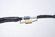
The "Thiele" R//L at the + Speaker Output Cable
Here the pictures of the Thiele network, resistor and inductor connected in parallel in the + output speaker cable. I used a 10 Ohm resistor and a 1.5uH inductor.
Here the pictures of the Thiele network, resistor and inductor connected in parallel in the + output speaker cable. I used a 10 Ohm resistor and a 1.5uH inductor.
Attachments
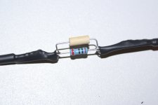
That inductor looks a bit small. Is that an iron core indcutor? Did you check the saturation current and DC resistance?
The saturation current should be greater than or equal to the amp output current. If the current drives the inductor core into saturation, you will get audible distortion. With your 40 V rails and 8 Ohm speakers the saturation current should at least be 4-5 A.
The saturation current should be greater than or equal to the amp output current. If the current drives the inductor core into saturation, you will get audible distortion. With your 40 V rails and 8 Ohm speakers the saturation current should at least be 4-5 A.
About 10Turns of 1.2mm enameled copper wire for the inductor.
It's resistance should read near enough zero ohms on most DMM set to ohmmeter.
I can't tell anything about the pics in post12.
We are back to the same problem: Retailers selling kits without any customer/builder support.
It's resistance should read near enough zero ohms on most DMM set to ohmmeter.
I can't tell anything about the pics in post12.
We are back to the same problem: Retailers selling kits without any customer/builder support.
... but it's cheap......Retailers selling kits without any customer/builder support.
API Delevan 1.5uH Inductor.
The inductor is a RF inductor API Delevan 1.5uH, 5% tolerance, maximum dc current 670 mAmps, maximum dc resistance 0.5 Ohms, self resonant frequency 160 Mhz and Q minimum 33, and it is "unshielded". This is the information I found at the place where I bought it from.
Here is the data sheet of the manufacturer:
http://www.delevan.com/seriesPDFs/1537.pdf
The seller of the speaker protection board replied with a *.doc file with instructions. It says that the board can be powered by 12-15 volts AC, the inputs are the holes/pads, and the outputs are the big holes where the speaker terminals connect to the board. I am attaching the *.doc file to this post. Please take a look at it.
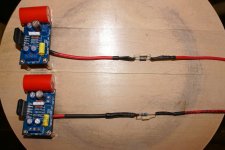
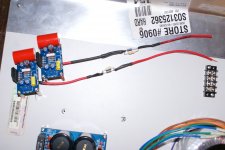
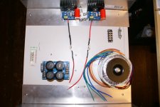
I am also attaching a picture of the boards mounted on top of an old PC desktop, this is just to test it, I will get a nice amplifier enclosure for all the stuff, but I'm dying to hear it. I am not using the input selector board yet.
Again, thank you very much AndrewT and Pacificblue, this would have never been possible without your help.
The inductor is a RF inductor API Delevan 1.5uH, 5% tolerance, maximum dc current 670 mAmps, maximum dc resistance 0.5 Ohms, self resonant frequency 160 Mhz and Q minimum 33, and it is "unshielded". This is the information I found at the place where I bought it from.
Here is the data sheet of the manufacturer:
http://www.delevan.com/seriesPDFs/1537.pdf
The seller of the speaker protection board replied with a *.doc file with instructions. It says that the board can be powered by 12-15 volts AC, the inputs are the holes/pads, and the outputs are the big holes where the speaker terminals connect to the board. I am attaching the *.doc file to this post. Please take a look at it.
I am also attaching a picture of the boards mounted on top of an old PC desktop, this is just to test it, I will get a nice amplifier enclosure for all the stuff, but I'm dying to hear it. I am not using the input selector board yet.
Again, thank you very much AndrewT and Pacificblue, this would have never been possible without your help.
Attachments
- Home
- Amplifiers
- Chip Amps
- Bought a XY LM3886 Kit.