Hi AndrewT:
The RF capacitor is 0.001uF (not 0.01uF), I bought it taking the value from your previous post, where you recommended a capacitor from 220pF to 1nF. I decided to go with the higher values of all your recommendations, since I couldn't find any 1nF capacitor listed in any of the online catalogs because they use uF values, I used an online calculator that produced the 0.001uF equivalence to 1nF. Is this then right?.
Yes, I know what you mean with the "blob soldering joins", I have to get better at this, I was practicing a lot before with old PCB boards I have from computer upgrades, soldering and desoldering, this is my first time doing this, but yes, I know I need to get better.
Let me know about the 0.001uF, which according to the calculator I used is equal to 1000pF.
Thank you!
Lanchile, thanks for the advice, I cleaned the boards with 91% alcohol before soldering, also the legs of all components, and most of them got scraped when I inserted them into the holes, since I used bigger 1/2 watt resistors, the legs were a little tighter in the board's holes. I don't have any cold joints, I think that what AndrewT is saying is basically that I used too much solder in some of the joints on the upper side of the board. I need to get better at soldering components together (not through hole) using less solder.
Fabricated, all the amp chip legs are very well soldered at the bottom of the PCB, I checked every solder joint using a very strong LED flashlight, when I place the flashlight right under the PCB, I can't see any light filtering through the LM3886 or any other component's hole.
I appreciate your observations and suggestions anyway, thank you.
AndrewT:
I received the capacitors today. I am kind of dissapointed, I ordered 100uF 50V Elna Silmic II, they are too big for the board, I cannot use them. I guess I will have to save them for a future project. I will have to use the Nichicon 100uF 50V Audio type I ordered before, they fit the board perfectly, same value but much smaller in size then the Elna Silmic II.
I also got 22uF 50V Elna Silmic II, and 47uF Elna Silmic II. Those fit the board perfectly, and they will go in the space for C4, the problem is that I am unable to use the equations you gave me to calculate those values.
I always try to do research on everything you guys tell me here, but most of the times, the more research I do, the more complicated and confussing things get.
The resistor I used for the Zobel in location R1 is 10 Ohms. The resistors in locations R2, R3 and R5 are 22K Ohms. The ones in locations R4 and R6 are 1K Ohms.
So far, every kit I've seen and most of the builds use 100uF capacitors in locations C1, C2 y C3.
The problem is in locations C4 and C5. My kit came with low quality 22uF 50V capacitors for location C4. I have better ones in that value, and also the other option I've seen used, 47uF 50V.
The C5 capacitor I got is the MKP 4.7uF 400V polypropylene type, the one I've seen recommended in most of the research I've done. They say to use either a 3.3uF or better 4.7uF MKP type.
I am using a 28V toroidal transformer that will produce 40V of DC, to drive a pair of B&W DM220 speakers.
Which capacitors should I solder????
Thank you again, Andrew!!!! Sorry for asking so many questions.... I wish I had 1/32 of your knowledge....
I have suggested in the past that a 240:28+28Vac transformer used on a 240Vac mains supply might just be OK to power a 3886.
I got shot down in flames.
But I still hold that view.
most transformers are now 115/230:28+28Vac. These will power a 3886 when the mains is 110/220Vac.
If the mains is 115/230 then you end up in exactly the same situation as my opening sentence.
If the mains is 120/240Vac, then in worst case conditions you may damage the chipamps.
You must check your worst case voltage at the smoothing capacitors !!!!!!!!
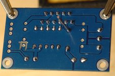
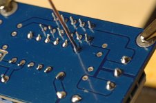
a sharp knife, or craft knife, or scalpel can all be used to cut the bridges. Just take your time and use a magnifier if you need such.Good job on cutting the three ground "straps?" around the bottom side of C4, that is not easily done.
AndrewT:
The AC voltage here in USA is 120V. When I measure the actual voltage coming out of the wall outlets, I get a reading of 124.7 volts. I have read that a difference of +/- 10% in mains AC voltage wouldn't make any difference. My 10% would be 11.5 volts since the transformer is rated at 115V AC. Which means that I'm still save at 124.7 volts, since 115 volts plus 11.5 volts is 126.5, and I am at 124.7, correct?.
The AC voltage here in USA is 120V. When I measure the actual voltage coming out of the wall outlets, I get a reading of 124.7 volts. I have read that a difference of +/- 10% in mains AC voltage wouldn't make any difference. My 10% would be 11.5 volts since the transformer is rated at 115V AC. Which means that I'm still save at 124.7 volts, since 115 volts plus 11.5 volts is 126.5, and I am at 124.7, correct?.
a sharp knife, or craft knife, or scalpel can all be used to cut the bridges. Just take your time and use a magnifier if you need such.
I used a Dremel with a 25mm dia. cutting wheel. It was easy, it just took two seconds in each cut, but the cutting wheel is too big, it can be done much better with a smaller diameter cutting wheel, I just didn't have one at the time...
It's not necessary to scrape the legs. Do you know any pro doing that?Before soldering ALWAYS scrape legs of parts until they get shiny and the same goes to boards, that way it will make good joins. Be aware of cold soldering!!!
a 115:28+28Vac transformer running on 120Vac and then a +6% for maximum supply condition and you will be over the 84Vdc max of the 3886.AndrewT:
The AC voltage here in USA is 120V. When I measure the actual voltage coming out of the wall outlets, I get a reading of 124.7 volts. I have read that a difference of +/- 10% in mains AC voltage wouldn't make any difference. My 10% would be 11.5 volts since the transformer is rated at 115V AC. Which means that I'm still save at 124.7 volts, since 115 volts plus 11.5 volts is 126.5, and I am at 124.7, correct?.
post54 explains.AndrewT:
Did you read post #69 regarding the C4, C5 capacitor values?
What part needs further explanation?
The only time I scrape lead legs for soldering is when I can see an insulating film over the solderable end.
That insulating film could be the enamel of wire or it could be one of the copper oxides.
If the lead legs are tinned or tin plated or silver plated then as soon as the hot solder and the hot flux flows over the wire end the flux boils off any of that soft corrosion. That's why they sell us pre-coated ends on the leads.
BTW,
I do not have a solder pot, nor a way of ensuring the pot temperature suits the next soldering job. For these reasons I do not trust the claim of self soldering insulations on some enameled wires.
Last edited:
AndrewT:
Using the second equation in post #54, using C5 as 4.7uF, I have a result of 48.86, which would indicate to use the 47uF 50V capacitor in C4 instead of the 22uF 50V recommended in the kit, is this correct?.
I couldn't really determine the value of C5 using the previous equation you posted in post #53, I don't even know what "Low Frequency Response" to choose for the amplifier, this is way beyond my level of knowledge, that's why I included all the info I could, even the speakers I will be using to play music with this amplifier.
Again, I used all the values recommended (22K Ohm, 1K Ohm and 10 Ohm for Zobel)) in the resistors, I just upgraded them to 1/2 watt.
Now, back to the dilemma, is it OK then to use a 47uF 50V cap in C4 location and the 4.7uF MKP in C5, or should I use the 22uF in C4?.
It's not necessary to scrape the legs. Do you know any pro doing that?
working with a technician who has been in this business for more than 30 years I learned that scraping legs ( caps, resistors, diodes, transistors etc) will ensure you will have a better join. it is like a plummer when they solder those copper pipes and they ALWAYS scrape with sandpaper making sure is shiny to make better contact and then they solder. beside it will not take too much time. He used to test and measured parts before and after soldering parts . I also learned how to solder STK's and IC's.(many legs) He said for example, if a chip has 12 legs, I should solder leg 1 then leg 12...2 then 11...3 then 10....etc and always not rushing the job. That way you do not "concentrate" all the heat on one side (unless you want to wait a little bit from soldering). I know many will jump here saying that is BS, But to me I find it smart!. You solder your way and I solder my way right?. I learned a lot from him, and staff that you do not learn in a electronic school. I guess you learn by experience and mistakes. I read Bryston technicians Do test the parts before and after they solder them, so I guess my friend was not so wrong after all.
- Home
- Amplifiers
- Chip Amps
- Bought a XY LM3886 Kit.