Andrew:
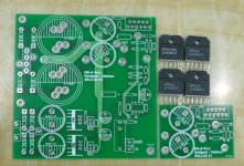
Today I received the new boards, let's call them the Pemo boards since he's the one that "discovered" them... You were absolutely right, ALL grounds on the board are connected, the input ground has to be isolated same as with the XY boards. These boards are bigger, I'd say about 10mm wider and 7mm longer than the XY's.
I will post pictures of these soon, both sides. I believe I know where the bridges need to be cut, I will tell you when I post the pictures so you can correct me if I'm wrong.
They look better than the XY's, the only problem I see is the location of the input AC coupling capacitor (C capacitor in National's datasheet), the space is too small to use same type of capacitor as in the XY boards...
Have you measured the noise and offset at the outputs of any of your amplifiers?Very light, I have to get my ear very close to the tweeters to hear it,
Your calculation for the LF filter (high pass) is correct.I have another question for you guys.
It has to do with this equation, you posted it here before:
Fc=1/(2πRiCi)
I tried to figure it out with these new amps I built, that in values, the only difference is in Ri (R4) in the PCB. New Ri is 680 Ohm, old Ri was 1K Ohm.
When I did it with the old amp value, I got this:
Fc=1/(6.28318x1000x47)
Fc=1/295309.46
Therefore, Fc=3.386Hz
Now, when I did this using the Ri value of 680 Ohm used in the new amps, I've got the following:
Fc=1/(6.28318x680x47)
Fc=1/200810.4328
so Fc=4.979Hz
Is this correct?.
Now the reason for the question. I've been listening to the new amps for a few days now, they sound good, but in my opinion the treble is too bright, the old ones sound better, more balanced, this is really hard to express in words but the sound of the old ones feel more harmonic. The new ones sound great too, but the high frequencies shine too much. Is that equation above the one to blame for that?.
Can you guys elaborate a little bit more on these low pass, high pass, -3dB concepts?. I've been reading on my own, but I can't get it. In this specific case, one amp has 3.386Hz and the other 4.979Hz, how does that translate into simple practical easy to understand terms?.
I find that even small speakers can sound better if the amplifier response extends well below audibility. I now habitually aim for ~90ms at the input filter. That requires >=135ms at the NFB filter.
For a 680r in the lower leg, that requires (for my listening preferences) the cap to be >=190uF, i.e. use 220uF or 330uF. Your 47uF is fully two octaves higher than what I like.
As far as your ears are concerned, cutting the bass has the same effect as, boosting the mid and treble.
Andrew:
I have no way of measuring noise, I don't have the hardware to be able to do that.
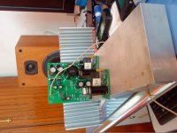
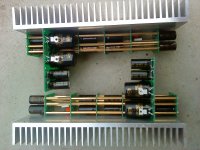
The DC offset is left channel 0.001V and right channel 0.004V. What I see is that there is continuity in the + and - speaker terminals. The + come from the amp's outputs, the - are connected from the chassis to the star GRD. The speaker terminals, if you see my pictures, are isolated from the chassis with plastic washers.
Is this normal?.
Thank you for your reply regarding calculation of Fc, I still need more help on the subject, the problem is that I have to leave now but I'll post my questions as soon as I get a chance. I think this is the most important thing that one needs to understand before putting these amps together. It is not about soldering stuff on a board...
And once again, I thank you very much for sharing your knowledge with so much dedication and patience here with all of us, thanks for being so generous, I really appreciate all the help you have provided us.
I have no way of measuring noise, I don't have the hardware to be able to do that.
The DC offset is left channel 0.001V and right channel 0.004V. What I see is that there is continuity in the + and - speaker terminals. The + come from the amp's outputs, the - are connected from the chassis to the star GRD. The speaker terminals, if you see my pictures, are isolated from the chassis with plastic washers.
Is this normal?.
Thank you for your reply regarding calculation of Fc, I still need more help on the subject, the problem is that I have to leave now but I'll post my questions as soon as I get a chance. I think this is the most important thing that one needs to understand before putting these amps together. It is not about soldering stuff on a board...
And once again, I thank you very much for sharing your knowledge with so much dedication and patience here with all of us, thanks for being so generous, I really appreciate all the help you have provided us.
Mine is good DMM...
Andrew, mine is a good, decent multimeter, it measures resistance, diode, voltage and capacitance, the only thing it doesn't measure is inductance and temperature. It does many things, but I haven't really learned how to use them all. I think that by what you say, I should be able to measure noise, I just don't know how to do it.
Can you please help me with that?.
I have a variety of cheap to very cheap DMMs. All can measure the noise at the output of my power amplifiers.
Andrew, mine is a good, decent multimeter, it measures resistance, diode, voltage and capacitance, the only thing it doesn't measure is inductance and temperature. It does many things, but I haven't really learned how to use them all. I think that by what you say, I should be able to measure noise, I just don't know how to do it.
Can you please help me with that?.
The Power Ground to Signal Ground mod is identical to what has been discussed in detail.
Yes, but the location is different, because the PCB layout doesn't look anything like the XY PCB, I just want to make sure we are on the same page before cutting any bridges, I think I know where those cuts need to be done, but I need you to confirm it, and I also want to post pictures here with the instructions so others can do it too. I want this thread to be the best way to learn and master the LM3886 chip with the chinese boards, that's why we need you to be around, dear Professor...
Set the DMM is 200.0mVac.
If the noise exceeds 10mVac, then something is seriously wrong.
If the noise is in the range 2mVac to 9.9mVac, then the amp is bad.
If the noise is in the range 0.3mVac to 1.9mVac them is is moderate. (-80dB to -90dB ref 20Vac).
If it is <0.3mVac then it is good. (better than -98dB ref 20Vac)
If it is <0.1mVac, then it is bordering on excellent. (better than -112dB ref. 20Vac)
And forget Prof. or any similar inappropriate titles.
Andrew:
I measured the AC mV's in the output terminals. I've got the following readings:
Left Channel=1.7mV Right Channel=2.6mV
I understand that according to your last post, then the Right Channel amp is bad, but this is the same amp you've seen in the first set of pictures I posted here, and when I used them both before replacing them with the new ones, even with the wiring being a total mess with no "twisted pairs" and no separation of signal path from power path, there was no audible noise of any kind in those amps.
This is driving me crazy...!
I know this is unrelated, but when you mentioned measurement of noise, I thought you were going to tell me to set my DMM to Hz. I forgot to mention that is has a button to select Hz measurements, when I depress it, it shows K Hz on the screen, what is that for?. I know is Hertz, which translates to cycles per second, but in a DMM, what is it used for?.
Regarding the "P" word, it was never my intention to annoy you or to offend you, on the contrary, I believe you deserve it for the high level of knowledge you have and the generous and dedicated way you have decided to share it. But I won't use it anymore.
0.002Vac or 0.002mVac?
I checked it again and I kept meter for a while and it moved from 0.001Vac to 0.002Vac. it stays around 80% of the time on the 0.001Vac side!
Last edited:
I checked it again and I kept meter for a while and it moved from 0.001Vac to 0.002Vac. it stays around 80% of the time on the 0.001Vac side!
I am assuming it was an analogue meter?
What scale was it on, 1V? Or e.g. 10mV?
The specifications of the multi- or voltmeter will often tell you that the measurement has a certain possible error. If it had been a digital meter and you actually read 0.001V, the error in the measurement probably is big enough so that the actual voltage might be 0.00001V or 0.003V.

- Home
- Amplifiers
- Chip Amps
- Bought a XY LM3886 Kit.