They will do the job, but are unnecessarily big and expensive. Find some ceramic caps, the cheapest will do, because they operate so far above audio frequencies that THD, tolerances or temperature coefficients don't matter. If you prefer film caps, use smaller and cheaper ones.I have some WIMA MKP10 100nf (400V) capacitors left. Are the OK to use for the Zobel?
At least 2-3 cm away from everything that carries AC to avoid crosstalk. AC is in mains and audio cables, traces, wires, etc.Where to put the other half of the Thiele network? close to amp board or close to the speaker connector in the chassis?
That resistor should be a bit sturdier, because it is supposed to protect the amp when capacitive loads are connected. Those have extremely low impedance at high frequencies and the resistor is there to limit the current. It need not sustain the full output voltage for long. For such an amp it should be rated between 2 and 5 W.What is the minimal wattage for the resistor in the second part of the Thiele network?
If you want to make them yourself, have a look in the class D section. They usually need output inductors with high current rating for their output filters.So the saturation current for the inductor should at least be 4-5 A. Such inductors are hard to find. where can I buy them? Or can I make them easily myself.
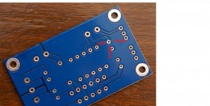
Answer is in post #27.What is the use of the copper wire on the top side that is to be soldered onto the output PIN? Is this nessecary?
You need that only for single supply amps. Their output voltage for zero input is half the supply voltage, and that must be filtered out to avoid damaging the speakers.There is also a large capacitor in the output line. Why?
I see 4 pads connected to the bottom side common ground.
Look and see that C4 -ve pin is connected to the common ground.
If you are building a single channel or monoblock then this connection demands that the Main Audio Ground (MAG) must be on the PCB.
If you want the MAG to be elsewhere or you intend to have more than one channel in the chassis then that C4 must be cut from the common ground.
Carefully cut the three trace bridges. Leave the pad intact. The Signal Ground will now be made at the GND terminal next to the IN terminal.
I want to build a two channel amplifier into one chassis. You where telling Aguilabrava that three trace bridges must be cut.
Could you or anybody else explain to me why this is necessary when building a amplifier with more then one channel in the chassis? Others here have build this amp without cutting these traces and their amps seem to work just fine.
I marked some areas with arrows in the image that I borrowed from Aguilabrava. Are this the trace bridges to be cut?
I already have the components soldered to the board, would this be any problem?
Attachments
Last edited:
Thanks Pacificblue for answering my questions! That's all clear now!
To Aguilabrava: I'm not intending to hack this thread you started, but since we are building the same amp and I'm having some unanswered questions I felt free to get in. I have already found a lot of answers on your thread!
To Aguilabrava: I'm not intending to hack this thread you started, but since we are building the same amp and I'm having some unanswered questions I felt free to get in. I have already found a lot of answers on your thread!
I believe the bridges are cut to seperate the power ground plane from the signal ground
I understood that already, but why does this need to be done when using more then one channel in one chassis and why does this not when building a monoblock?
In a monoblock, where one has just one channel of amplification there can never be interchannel currents flowing.
In a multi-channel amplifier, there can be many cross connections for inter-channel currents to flow. The problem is identifying them and ensuring that the currents that do flow, do not cause any audio voltages to be generated.
This is where separating the Signal Ground from the Power Ground becomes of importance.
In a monoblock, where one has just one channel of amplification there can never be interchannel currents flowing.
In a multi-channel amplifier, there can be many cross connections for inter-channel currents to flow. The problem is identifying them and ensuring that the currents that do flow, do not cause any audio voltages to be generated.
This is where separating the Signal Ground from the Power Ground becomes of importance.
Thanks for your answer. Could you please also answer my question regarding the bridges that have to be cut. See the image in post 183.
Has this amplifier a asymmetrical or symmetrical power supply? I'm asking this because I'm also building a speaker protection kit. If the amp uses a asymmetrical power supply 1 W vertical resisters are needed on the speaker protection board. When the amp has a symmetrical power supply these resistors may NOT be mounted!
......This is where separating the Signal Ground from the Power Ground becomes of importance.
............... Could you please also answer my question regarding the bridges that have to be cut.
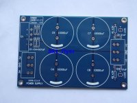
It should have a symmetrical = split power supply, but effectively it depends on you what you build.
There was a split power supply pcb that came with this amp. So it is symmetrical. Thanks.
Attachments
I'm back....
Corpius:
Feel free to post anything related to XY LM3886 here, I don't see it as you hacking anything, on the contrary, I thank you for your contribution.
Regarding the bridges that have to be cut, I posted pictures in this thread so AndrewT and Pacificblue don't have to be answering the same questions over and over...
I am sorry I haven't posted the pictures of the working amplifier, I have been busy working, and enjoying the great sound of the ANDREWT/PACIFICBLUE amp I have now... But I promise I will be posting them soon.
Pacificblue:
I am going to need more details on those add-on things I need to control the two 15 volts secondaries.
Thank you to all of you...!
15 V Secondaries.
Pacificblue:
I believe I am going to need the two 15 volts secondaries, since one will feed the "speaker protection board" and the other one will feed the "input selector board"...
Thank you for your help, the more I listen to this thing, the better it sounds...
You only need one of the two 15 V secondaries.
Pacificblue:
I believe I am going to need the two 15 volts secondaries, since one will feed the "speaker protection board" and the other one will feed the "input selector board"...
Thank you for your help, the more I listen to this thing, the better it sounds...
BAD NEWS....!
Hi Guys:
I have some sad, bad news...
This morning I was listening to the A/P (AndrewT/Pacificblue) amplifier, the volume like 3/4 of the way up, and suddenly, the Left channel stopped working.
I started turning the volume pot up and down and realized that the Left channel comes back when the volume is at the full volume, all the way up position, but not as powerful as the Right channel.
I checked the voltages of the PSU and amplifiers, and everything is fine, 80 volts when measuring +V to -V, and 40 v when measuring from any of the V's and GRD.
I switched the + input cables from one amplifier to the other and the problem remains in the Left channel amplifier.
I removed the Left channel amplifier from the improvised chassis where I have it and check resistance and capacitance of every component on the PCB and all the readings I've got are correct.
What could be causing this problem?.
Is there anything to measure in the LM3886 that could help me determine what the issue is?.
Thanks again...
Thanks, AndrewT.
Hi AndrewT:
I thought it could be the volume pot, but since it is brand new, and I switched the + input cables and the problem remained, I assumed it was the LM3886TF chip.
Now, after reading your post, I checked both input connector blocks on each amplifier, with the volume all the way up I get the following readings:
91.3 KOhms in "bad amplifier", and 100.5 KOhms in "good amplifier", would this indicate a bad volume pot?.
If I do the same measurement with the volume pot in the half way position, I get 13.58 KOhms in "bad amp", 16.20 KOhms in "good amp".
With the volume in the zero volume, no audio position, I get 2.5 Ohms in "bad amp" and 2.0 Ohms in "good amp".
I checked for continuity in "bad amp" PCB and everything seems to be connected....
- Home
- Amplifiers
- Chip Amps
- Bought a XY LM3886 Kit.