I had a similar problem sourcing chassis wire. My transformers had 18ga 600V wire at the primaries and 16ga 600V wire at the secondaries. It is hard to find 18ga 600V stranded wire in small quantities. All of what I found is 300V. Now my cord from the wall to the iec is 18ga 300V stranded. I saw no reason to try and source wire rated at 600V. Hopefully the wire will never see voltage over what it is rated to. Hope this helps. I got my wire from parts express.
600V rated cable is generally specified for 220/240Vac mains wiring.
I don't know your standards , but it may be that 300V rated cable is ok for 110/120Vac mains wiring.
The two colour insulation is usually the manufacturers' way of achieving double insulation for the mains wiring. It is generally not used on the Secondary side.
I don't know your standards , but it may be that 300V rated cable is ok for 110/120Vac mains wiring.
The two colour insulation is usually the manufacturers' way of achieving double insulation for the mains wiring. It is generally not used on the Secondary side.
Duh. Why didn't I think of that? Never thought of taking an old PC power cord and using the internal wires. I certainly have plenty laying around. Actually, a whole box full of them!I have tried to try the same thing till I realized, if the AC wires feeding the transformer were carrying the full power to the transformer, they certainly could handle the reduced amount. Now I just strip one of the many PC style power cord lying around and use that wire. I cut the transformer leads to a length that is appropriate and transition with a Euro-style screw terminal. Works for me.
I actually cut these too short but still works.
View attachment 275733
 Anyway, like I said, I've ordered some other 16 gauge hook-up wire. I do however like the thickness of my tranny's secondary leads which are rated at 300v. Just can't find any.
 Yep. I'm using 120Vac mains so 300v rating is okay. On 2nd inspection the secondary windings do not have the white inner insulation, just thicker outer wall. I'm sure what I have will work, just wanted a little heavier cable going from the PSU to the amp - even if only at +-60vdc. I'm waiting for another order to arrive and hopeful that the 16 gauge wire will be heavier.600V rated cable is generally specified for 220/240Vac mains wiring.
I don't know your standards , but it may be that 300V rated cable is ok for 110/120Vac mains wiring.
The two colour insulation is usually the manufacturers' way of achieving double insulation for the mains wiring. It is generally not used on the Secondary side.
Hi all, Here's the latest installment of my build....
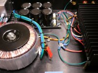
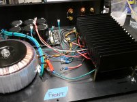
I've finally completed the wiring and testing of the amp module and speaker protection board. I've included a few photos below. Photos of the complete build can be found here.
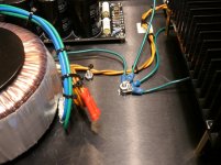
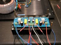
Since the last update I completed wiring and installing the amp module. This had not been tested before today. This module is being feed + and - 60volt rails (no load). I haven't checked the voltage under load yet, to see how the PSU is holding up.
Once the amp was in place I finished the wiring to the speaker protection board, and the RCA inputs along with the output binding posts. I wasn't happy with my soldering job on the binding posts, because they are heavier then the RCAs and my soldering pencil just wouldn't cut it. Good enough to test, but I do need a heavier wattage iron, or even a small gun to get the required heat.
Soooooo... after everything was in place, all wiring double and triple checked it was time for the big test. Since I had fired up the PSU before, I knew the output voltages were spot on +- 60v. It was now time to test the amp module. In went the power cord, on went the switch and after I heard the speaker relay click there was no smoke to be seen! Not even a spark.
I then proceeded to measure the voltages at the speaker terminals. Both channels right around 3.4mv - give or take a tenth. I was pleased. I let it warm up for a few minutes and took another reading. Still very low and very acceptable readings.
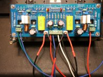
So now it was time to hook up some speakers and give it a sound test. This is was what I've been waiting for! So, I hooked up some speakers, used my minidisc player as source and connected directly into the amp. Turned everything on, waited for the relay click, and voila. Pure, beautiful music. And the best part of it all - not even the slightest hint of any hum. I guess, good design, proper grounding techniques and meticulous wiring all paid off. Now I'm even happier.
The amp is pretty much done now, except for bringing a LED out to the front panel. I guess I need to know when it's powered on. I will say, while I let it run for a few minutes this afternoon, the heat sink did start to warm up, but never hot to the touch. Of course, it was never really under any stress either. That will come later. Anyway, I'm pleased with result, and look forward to putting it to use in one of my systems after I finalize a few things and close it up.
I've finally completed the wiring and testing of the amp module and speaker protection board. I've included a few photos below. Photos of the complete build can be found here.
Since the last update I completed wiring and installing the amp module. This had not been tested before today. This module is being feed + and - 60volt rails (no load). I haven't checked the voltage under load yet, to see how the PSU is holding up.
Once the amp was in place I finished the wiring to the speaker protection board, and the RCA inputs along with the output binding posts. I wasn't happy with my soldering job on the binding posts, because they are heavier then the RCAs and my soldering pencil just wouldn't cut it. Good enough to test, but I do need a heavier wattage iron, or even a small gun to get the required heat.
Soooooo... after everything was in place, all wiring double and triple checked it was time for the big test. Since I had fired up the PSU before, I knew the output voltages were spot on +- 60v. It was now time to test the amp module. In went the power cord, on went the switch and after I heard the speaker relay click there was no smoke to be seen! Not even a spark.
I then proceeded to measure the voltages at the speaker terminals. Both channels right around 3.4mv - give or take a tenth. I was pleased. I let it warm up for a few minutes and took another reading. Still very low and very acceptable readings.
So now it was time to hook up some speakers and give it a sound test. This is was what I've been waiting for! So, I hooked up some speakers, used my minidisc player as source and connected directly into the amp. Turned everything on, waited for the relay click, and voila. Pure, beautiful music. And the best part of it all - not even the slightest hint of any hum. I guess, good design, proper grounding techniques and meticulous wiring all paid off. Now I'm even happier.
The amp is pretty much done now, except for bringing a LED out to the front panel. I guess I need to know when it's powered on.
I will say, while I let it run for a few minutes this afternoon, the heat sink did start to warm up, but never hot to the touch. Of course, it was never really under any stress either. That will come later. Anyway, I'm pleased with result, and look forward to putting it to use in one of my systems after I finalize a few things and close it up.Attachments
Hi Boscoe, Thanks. I got it from an eBay vendor in China. Here's a link to the amp module and his site. I've been very pleased with the quality of stuff he offers and his store is full of DIY kits, amps, DACs, enclosures, parts, etc. Some are full kits, others partially assembled, and still others ready to go right out of the box! I've written him several times via email, and he's very helpful and has even allowed me to order some key parts in larger quantities - just for asking. Shipping is expensive, but he has worked with me to combine items for shipping and sent airmail (DLH).Very nice build you got there.
Did you get the amp direct from the xd218.com website? If so how and what currency is it in? Chinease yuan?
I did visit the xd218.com site once, but found it is mostly in Chinese - even with the help of Google translate. Don't know if he's associated with xd218, or if it's his brick & mortar company in China. Most of what he quotes on his website is in USD, but I have seen a few items listed in pounds.
I've still got a little work to do on the amp, but for the most part it's complete. It took awhile, but I've been in no hurry, and had to wait for several shipments to show up from China. I'm still stocking up on some of the everyday DIY parts, as I hope to build some other things along the way. They're definitely not the Heathkits I used to put together years ago, but it's all fun. - Rick
Edit: One other thing... I believe this amp module can also be purchased in full kit form for a few less $.
Last edited:
In my stash of power cords I've found at least three different gauges that fit various applications. Problem is you have to cut off one end to see what's actually there.
Why don't you just measure the dc resistance of the cable ? No need to cut it open !
Hi Boscoe, Thanks. I got it from an eBay vendor in China. Here's a link to the amp module and his site. I've been very pleased with the quality of stuff he offers and his store is full of DIY kits, amps, DACs, enclosures, parts, etc. Some are full kits, others partially assembled, and still others ready to go right out of the box! I've written him several times via email, and he's very helpful and has even allowed me to order some key parts in larger quantities - just for asking. Shipping is expensive, but he has worked with me to combine items for shipping and sent airmail (DLH).
I did visit the xd218.com site once, but found it is mostly in Chinese - even with the help of Google translate. Don't know if he's associated with xd218, or if it's his brick & mortar company in China. Most of what he quotes on his website is in USD, but I have seen a few items listed in pounds.
I've still got a little work to do on the amp, but for the most part it's complete. It took awhile, but I've been in no hurry, and had to wait for several shipments to show up from China. I'm still stocking up on some of the everyday DIY parts, as I hope to build some other things along the way. They're definitely not the Heathkits I used to put together years ago, but it's all fun. - Rick
Edit: One other thing... I believe this amp module can also be purchased in full kit form for a few less $.
Thanks for the info but I'm always cautious when buying from china, I've had a lot of crap in the past.
I have to say I've been impressed with the quality of most of the pieces I've purchased from his site. Except for a recent DAC PCB I purchased (and it wasn't all that bad), the PCBs are top quality, and components appear to be genuine(?). And the assembled modules I've bought seem to be meticulously crafted. I'm sure there's plenty of junk out there, but I see that from other places too. I didn't buy this stuff on a whim, but carefully studied what I wanted, looked at the specs and inspected the pictures. I even emailed the vendor when I had questions, or wanted more clarification. He's actually been very good about following up with tech support from time to time. I'm willing to take a gamble on some things, and so far I'm pleased.Thanks for the info but I'm always cautious when buying from china, I've had a lot of crap in the past.
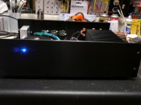
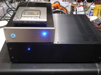
Hi all - Finalizing my build and wanted to include a few more pictures. The final wiring was to bring the power LED out to the front panel. Done! Now with the amp completed I can finally see it with the case close. Rather bland, but overall it will work nicely. I'm satisfied.
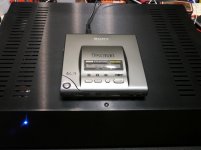
I did more testing the past couple of days and today I hooked up a new DAC unit I've built. I used the optical out of my aging Sony D-303 portable CD player. Not any critical listening per se, but wanted to hear a digital signal as the source input. I'm very happy with the sound. And I'm even happier that I can't audibly hear any ground loop hum. Even with several external pre-amps and sources I've tested with it, the amp is dead silent.
I did more testing the past couple of days and today I hooked up a new DAC unit I've built. I used the optical out of my aging Sony D-303 portable CD player. Not any critical listening per se, but wanted to hear a digital signal as the source input. I'm very happy with the sound. And I'm even happier that I can't audibly hear any ground loop hum. Even with several external pre-amps and sources I've tested with it, the amp is dead silent.
Attachments
Update.....
I later discovered I had a ground loop hum. Not sure how I missed that. It turned out to be how I had wired up the RCA inputs and how they were grounded. I re-did the wiring using both leads from the RCAs to the amp input connectors. I ended up using some standard unshielded, twisted pair from a CAT5 cable. This virtually eliminated all hum. Good results.
I later discovered I had a ground loop hum. Not sure how I missed that.
It turned out to be how I had wired up the RCA inputs and how they were grounded. I re-did the wiring using both leads from the RCAs to the amp input connectors. I ended up using some standard unshielded, twisted pair from a CAT5 cable. This virtually eliminated all hum. Good results.Question...Redjr,
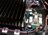
One of the green wire connections to the Main Audio Ground mounted to the chassis floor looks to me to be a link to the Mains PE.
That is wrong.
Change it.
(1) At some point in the design and layout do all 'grounds' come together - either through a star reference point, star of stars, or buss arrangement - as Dave Davenport illustrates in his excellent article here? Is that a true statement? While his article covers the topic in a much broader sense, he does discuss grounding strategy within a single component.
And I quote,
"4.1 - Grounding Rules
Here are some rules to help you plan your grounding structure. The first four rules are from what we learned about interconnecting equipment.
Rule 1: Each of the following must be connected to the system star ground by one and only one route.
All signal references
All power commons
Shields of non-galvanically isolated single-ended inputs and outputs
Safety ground and chassis. The safety ground and chassis should be thought of as a single entity.
The connection may be direct, or indirect through a star-of-stars or buss. This is expanded upon below.
The safety ground and chassis may be connected to the system star ground through a Safety Loop Breaker Circuit.
The “one and only one” part of this rule precludes ground loops. There is no excuse for a ground loop within a single component...."
I have reworked my grounding strategy to help better isolate my PSU ground and audio signal ground. I'm assuming, because some terminology is loosely used, and Dave often refers to 'system ground'. Is this the ground path between the PSU, amp and other modules that may be inter-connected inside a chassis, and then tied to the star ground at a single point? My audio signal ground from input to the speaker out remains isolated on the amp PCB and speaker protection PCB. They are only connected to the star ground at a single point. I have virtually eliminated all detectable hum that I can noticeably hear, or see without using equipment. I did not employ a Safety Loop Breaker Circuit.
I have included a pic of one of Dave's illustration and believe my grounding topology supports this method.
Attachments
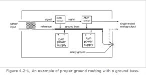
The problem that appears to show in the pic is that the chassis to PE connection is mixed in with all the other returns forming the Main Audio Ground (MAG).
There is nothing wrong with locating the MAG on the chassis.
I see the Chassis to PE connection as a SAFETY connection and by my reckoning it should be a permanent fixing at the mains input socket. For lowest impedance it must be a short wire. It should not have any other connection tied to it, otherwise there is temptation to dismantle the "permanent" connection that is mandatory.
There is nothing wrong with locating the MAG on the chassis.
It is the long PE to Chassis connection !One of the green wire connections to the Main Audio Ground mounted to the chassis floor looks to me to be a link to the Mains PE.
That is wrong.
I see the Chassis to PE connection as a SAFETY connection and by my reckoning it should be a permanent fixing at the mains input socket. For lowest impedance it must be a short wire. It should not have any other connection tied to it, otherwise there is temptation to dismantle the "permanent" connection that is mandatory.
Last edited:
Ok. I understand what you're saying now. You are correct, there is a long green lead from the IEC connector (PE) to my star point. That's an easy fix. I can simply tie it to the chassis using a much shorter lead. Problem solved!The problem that appears to show in the pic is that the chassis to PE connection is mixed in with all the other returns forming the Main Audio Ground (MAG).
There is nothing wrong with locating the MAG on the chassis. It is the long PE to Chassis connection !
I see the Chassis to PE connection as a SAFETY connection and by my reckoning it should be a permanent fixing at the mains input socket. For lowest impedance it must be a short wire. It should not have any other connection tied to it, otherwise there is temptation to dismantle the "permanent" connection that is mandatory.
If you had a shorter length to the PE can you still connect your return points to the same point? My understanding of what I read in the grounding article is that you could as long as your safety earth to chassis point was secured under its own dedicated nut on the stud. I think part of the issue is that all of your ground points share the same securing nut. It is a safety issue, but should function the same?
I used a similar ground scheme in my amp. All my pcbs have star ground on board and one reference from each board to the chassis. These two references are connected to the ground stud above the dedicated PE connection. My PE ground is a third of the length of my other ground references. This is the method recommended by Peter Daniel. I have not looked at your pcbs but would hope they have a similar on board star ground.
I used a similar ground scheme in my amp. All my pcbs have star ground on board and one reference from each board to the chassis. These two references are connected to the ground stud above the dedicated PE connection. My PE ground is a third of the length of my other ground references. This is the method recommended by Peter Daniel. I have not looked at your pcbs but would hope they have a similar on board star ground.
- Status
- This old topic is closed. If you want to reopen this topic, contact a moderator using the "Report Post" button.
- Home
- Amplifiers
- Chip Amps
- New LM4702 Build