Thank you for very detailed information..
This time I measure and found 0.9R resistance.
I build this LM1876 first time because I found several thread related to LM1875 and read somewhere LM1876 has two LM1875 having mute/stand-by function. In fact mute/stand-by function I could not build. At first impression I like LM1876 but long time listening I think I will not be able to live with it. My opinion it is just for pc multimedia speakers. If I push more voltage/gain chip becomes angry and over-heated. Or may be the reason I could not build as it should be.
Thanks & Best Regards.
0r0 plus the offset of your leads.
This time I measure and found 0.9R resistance.
I build this LM1876 first time because I found several thread related to LM1875 and read somewhere LM1876 has two LM1875 having mute/stand-by function. In fact mute/stand-by function I could not build. At first impression I like LM1876 but long time listening I think I will not be able to live with it. My opinion it is just for pc multimedia speakers. If I push more voltage/gain chip becomes angry and over-heated. Or may be the reason I could not build as it should be.
Thanks & Best Regards.
10 Ohm Resistor wound with 1mm enamelled copper wire 10 turn. When I check resistance of the inductor what value should show by my digital multi meter ?
0 Ohms is incorrect, if your meter goes down to 0.1 milliohm, or even if it goes to only 1 milliohm and the wire is greater than about one inch in length.
Any metal wire with non-zero length has a resistance greater than zero.
Resistance of any metal conductor is
R = pL/A,
where R is in Ohms, p is the resistivity of the metal (0.0000000168 Ohm-meters for copper at 25 C), L is length in meters, and A is cross-sectional area in square meters.
For your 0.0005-meter-radius copper wire, i.e. with A = .000000785 square meters cross-sectional area, that becomes
R = (0.02139) x (Length in meters), in Ohms.
For one inch (2.54 cm) of that wire, the resistance should be about 0.0005533 Ohms, at 25 C.
Note that if you measure it with the resistor that it's wound on, you would be measuring the parallel combination of them both (and anything else that's in parallel with them), which would change the expected measurement value.
Last edited:
Have a look at the deviation of your meter. It has a certain percentage calculated from the maximum value of the measuring range plus a certain amount of digits. The lower the measured value, the more difficult it is to get a precise reading with a standard DMM.This time I measure and found 0.9R resistance.
That information is wrong. The circuit is much more similar to the LM3886, except that the muting function works differently.read somewhere LM1876 has two LM1875 having mute/stand-by function.
Are you using single or split power supply? The 2,5 V refer to half supply, which means only with split supply they refer to ground. If you use single supply, you have to use a level shift circuit according to figure 5 from the datasheet.In fact mute/stand-by function I could not build.
Either that or the IC is a fake.
Thank you gootee
Thank you pacificblue, due to not getting expected results I was decided to move to LM4766 but your post stop me and try again.
I am using split power supply. i.e. 20 (+/-) VDC.
As per datasheet figure 5 : VCC = +20VDC , Logic Input = +5VDC and 10uf cap is for delay. Is this correct ?
Thank you pacificblue, due to not getting expected results I was decided to move to LM4766 but your post stop me and try again.
Are you using single or split power supply?
I am using split power supply. i.e. 20 (+/-) VDC.
As per datasheet figure 5 : VCC = +20VDC , Logic Input = +5VDC and 10uf cap is for delay. Is this correct ?
So what do you have?
Split power supply means no need for figure 5. In that case check, whether the amp is muted, when you connect Vcc to the mute pin. If it does your IC is OK and you have to check the mute circuit you tried before. If it does not, your IC is probably not an original LM1876.
Single power supply means you need figure 5. 100k and 10µ are for delay.
whether the amp is muted, when you connect Vcc to the mute pin.
Yes,
Hi pra3718, I think your amplifier is probably unstable. This is the most likely reason for lots of heat to be dissipated in output inductor. Check all your decoupling is correctly placed and soldered in. If possible borrow a oscilloscope so you can diagnose what is wrong. If you put a Zoble network on you have a good chance of stabilising the amplifier.
Regards,
Andrew
Regards,
Andrew
You don't need fancy error calculations, when dealing with low resistances and cheap DVMs. Even cheap DVMs are surprisingly accurate.This time I measure and found 0.9R resistance.
Did you followed Andrews advice and substracted the wire loop resistance?
If so, there is probably a problem with the enamelled wire. Soldering it is difficult and I usually use a blade and sand paper to remove the coating.
If so, there is probably a problem with the enamelled wire. Soldering it is difficult and I usually use a blade and sand paper to remove the coating.
I have faced this problem if soldering is not perfect then resistance value shows 10R.
Sorry to butt in here, but why do you want a gain of 48x? That is about twice what is normal and is almost certainly outside anything that National will have tested. What happens is that you use up the benefits of feedback because you are asking for too much at the output and there is only so much to go round. And you don't even get more power anyway, because that is decided by the rails for the most part.
I would say to go back to the usual 26dB gain (20x) and you will likely have a much more stable (and therefore better sounding) amplifier.
I would say to go back to the usual 26dB gain (20x) and you will likely have a much more stable (and therefore better sounding) amplifier.
there is much conjecture that the 3886 performs better at gains around 26times to 30times. In the 3886's case this is because the higher gain increases the amplifier's stability margins.I would say to go back to the usual 26dB gain (20x) and you will likely have a much more stable (and therefore better sounding) amplifier.
I suspect the 1876 will also respond to higher gain by showing increased stability margins. This is the exact opposite to what you stated.
The inductor||resistor should be as close to the chip as possible.
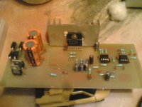
It might be very helpful if you could show your hardware layout.
It sounds like something might be oscillating at high frequency, causing the chip to run hot. How far are your smallest decoupling caps from the chip's power pins? And wherever there are resistors that are in series with chip pins, especially the input pins, how far from the chip's pins are they (in terms of total conductor length between part and pin)?
Gootee,
I don't agree that the inductor (R//L) needs to be located near the chip.
I contend that the part of the stabilising network (usually the first R+C) that passes VHF, MUST be located very close to the chip output pin and the chip's power ground.
OK. It might not "need" to be as close as possible. But the closer it is the better it probably is, since it also blocks RF from getting in through the output. Granted, most of the RF it stops will probably be coming in through the speaker wire. But leaving another length of "antenna" on the upstream side of the R||L is not desirable. However, I'll admit that the benefit might usually be negligible. I would still put it as close as was practical and easily implemented (i.e. "as close as possible"), for the times when there might be a nearby strong high-frequency RF source, which becomes more common every day.
I agree that the RC network should have higher-priority placement close to the chipamp output pin.
Last edited:
It might be very helpful if you could show your hardware layout.
Here is the photo copy poor but readable, Local decoupling caps 1000uf 25v added where red round described, and black round where I had added inductor. After burned I have removed and listening without them. You may advice for bigger heat sink.
Best Regards.
Attachments
- Status
- This old topic is closed. If you want to reopen this topic, contact a moderator using the "Report Post" button.
- Home
- Amplifiers
- Chip Amps
- Smoke at LM1876's output resistor having inductor