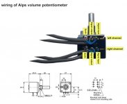
A new rig for volume control gizmo using Bare Alps 27 10K pot.
Bob, you moved from LDR to bare pot ? For me LDR is the first choice so far combined with a B1 buffer.
Last week a was shopping few russian capacitor from the guy recommended by Dario and am verry happy with results but as i changed the coupling capacitors in the same time to my MYREF, to my cd player and my RIAA preamp i can't say what is the benefit of every capacitor changed.
I bought:
1uF 250V 2% Hi-End Polystyrene capacitors K71-4 L
RARE!!! 0.047uF 200V PIO Capacitors K40Y-9
RARE! PIO Capacitors 0.1uF 200V K40Y-9
1.5uF 250V PIO caps K75-10 Lot of 4 Hi-End NOS
2.2uF 250V PIO Capacitors K75-10 Lot of 4 NOS Hi-En...
RARE! PIO Capacitors 1uF 200V K40Y-9 NOS/NIB
I found the guy is also selling some teflon ft-1 and ft-2 and i'm planning to buy some teflon to bypass this huge capacitors. I've heard teflons are sounding very good.
After a friendly discussion with seller he told me they source very cheap these old russian capacitors....but they know the source
") and we dont
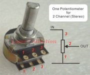
and we dont This is a good explaination. Picture #2 is from the eBay pot.
KSTR, I was looking at the TDK pieces this morning. I may add one to the collection soon.
ATUPI, Not moving at all, just collection all the options for a final selection to be made later. It most likely will be a combination of devices.
KSTR, I was looking at the TDK pieces this morning. I may add one to the collection soon.
ATUPI, Not moving at all, just collection all the options for a final selection to be made later. It most likely will be a combination of devices.
Attachments
Last edited:
KSTR, Google is failing me - can't find any info on "non-isolating RCAs". That's a oxymoron to me. Can you explain?
These Hammond Potting Boxes are plastic. Shouldn't they be metal? Or are you describing something different?
Can you explain?These Hammond Potting Boxes are plastic. Shouldn't they be metal? Or are you describing something different?
Last edited:

Last edited:
Thanks, So if I understand correctly, using the signal ground with continuity to the enclosure produces an all-encompassing mega shield?
A giant untwisted twisted pair.
Sorry Bob I am lost as to who you are thanking and what you are talking about...
Since I am very interested in the grounding plan, can you help me out with a few hints for a thicky?
Bill
Hi Bill, This is what I think I know. A twisted pair is acknowledged as a method to cancel interference. It is at the heart of high speed copper network cable (the length and angle of each single rotation being critical) and all sorts of audio applications. A form of self shielding.
For a separate/discrete volume pot (and maybe even one inside a chassis) that concept is just extended to include a big bulge that houses a pot along the path/wire pair . The cancelling characteristic of the negative/ground current is just applied to a box and then returns to a twisted pair. The use of a non-conductive knob on the shaft eliminates the psudo-grounding/continuity from the human body.
KSTR and/or Andrew will correct me if I'm mistaken.
If you really want to dig in look HERE
Last edited:
Another way to visualize the concept would be the signal - shield design of standard coax cable. The metal box that houses the pot simply acts like a balloning of the shield over a short distance. That is why a plastic box will not work.
Just to clear things up a bit more, this is not the same thing as the power and signal grounding arrangements on the actual PCB and the associated connections/isolations. This whole discussion probablly should have been over on the JA/JC-2 thread. If needed, we can continue over there. ....My bad.....
Just to clear things up a bit more, this is not the same thing as the power and signal grounding arrangements on the actual PCB and the associated connections/isolations. This whole discussion probablly should have been over on the JA/JC-2 thread. If needed, we can continue over there. ....My bad.....
Last edited:
Yes, that exactly is the point for efficient electrostatic shielding. Depending on the thickness of the aluminum housing and on how good the electrical contact is along the seamline(s) of the box and the lid(s) this will also afford good magnetic shielding at moderate and high frequencies.Another way to visualize the concept would be the signal - shield design of standard coax cable. The metal box that houses the pot simply acts like a balloning of the shield over a short distance.
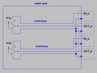
At low frequencies twisting all of the (short) signal lines per channel with the corresponding return (GND) lines does the job (but magnetic coupling is only an issue when the magnetic fields are very strong indeed), but you must take care not to build literal ground loops inside the box (keep the loop area of the GND connection wiring in itself as small as possible, that is, avoid any loops).
For the same reason the GND shall only be connected at one single point -- solder the four lugs of the RCA's together, the RCA barrels will provide the contact to the box.
For the outside world, twist all interconnects together, too, and at the point were you must split between input (source) and output (amps), keep the L and R lines together as much as you can.
Finally, route power cables also along that cable buss, again keeping all cables from/to a device together (interconnects with good shielding properties, and some experimentation is required.
It's all about keeping sending and receiving loop areas as small as possible.

Attachments
Last edited:
Klaus,
the My_Evo Rev A grounding scheme, which is the one I've intention to use, has a pseudo Class II approach:
A thing that I've yet to figure out is where to connect transformer's shield, chassis or safety earth.
Thanks in advance
the My_Evo Rev A grounding scheme, which is the one I've intention to use, has a pseudo Class II approach:
- Safety earth is not connected
- PCB power ground is connected to chassis
- RCA connectors are insulated from chassis
- R11 is, obviously, in place.
A thing that I've yet to figure out is where to connect transformer's shield, chassis or safety earth.
Thanks in advance
Hey Dario. I'm under the impression the info KSTR has posted is primarily for use with a separate self-contained pot that would be placed between a source and a power amp via interconnects. Something more useful in testing than in final application (though the shielding can be beneficial in all situations). Not the same as what you are describing in post #1133.
I'm also thinking "Safety earth not connected" has to do with hum as discussed earlier, but how does that effect the general safety/shock hazard present in any amp design? Does the PCB power ground to chassis address that?
I'm also thinking "Safety earth not connected" has to do with hum as discussed earlier, but how does that effect the general safety/shock hazard present in any amp design? Does the PCB power ground to chassis address that?
Hey Dario. I'm under the impression the info KSTR has posted is primarily for use with a separate self-contained
Sure, in fact I'm not asking Klaus about it but what he thinks of the Evo Rev A grounding.
I'm also thinking "Safety earth not connected" has to do with hum as discussed earlier, but how does that effect the general safety/shock hazard present in any amp design?
It's not directly related with hum, Mauro on his Rev A paper talks about 'weak interactions' (I've no idea what he mean).
A disconnected safety earth implies Class II construction (double insulation) which basically should mean that all precautions must be taken so that in case of a fault no high voltage is present on the chassis.
Does the PCB power ground to chassis address that?
No
O.K. Thanks.
Sorry to be so slow to understand, but what ground category/design is the Fremen Edition? Can you describe in a little more detail those "precautions" an FE builder should keep in mind.
Probably just basic stuff, but I fear I may have introduced a bit of confusion over my last few posts.
Sorry to be so slow to understand, but what ground category/design is the Fremen Edition? Can you describe in a little more detail those "precautions" an FE builder should keep in mind.
Probably just basic stuff, but I fear I may have introduced a bit of confusion over my last few posts.
O.K. Thanks.
As always, you're welcome Bob
Sorry to be so slow to understand, but what ground category/design is the Fremen Edition?
Class II is referred to chassis and the whole construction of the device.
Not directly related to the FEs.
Can you describe in a little more detail those "precautions" an FE builder should keep in mind.
It's what I'm trying to figure out too...
I suppose, for instance, that all power wires should be fixed, all power connectors are insulated, that all wiring is done so that in case a connector disconnects it can't touch chassis and so on...
Probably just basic stuff, but I fear I may have introduced a bit of confusion over my last few posts.
I don't think so.
O.K. Thanks.
Sorry to be so slow to understand, but what ground category/design is the Fremen Edition? Can you describe in a little more detail those "precautions" an FE builder should keep in mind.
Probably just basic stuff, but I fear I may have introduced a bit of confusion over my last few posts.
I know you are being overmodest Bob,... I will give my own 'parent of younger children' interpretation of grounding...
Any electrically conductive external part of a DIY audio project, which a person could conceivably touch, suck, bite, or lick, has to be connected to a robust safety ground by a physically secure crimped connection.
If you have noise as a result of following this grounding plan there must be ways of resolving it without potentially killing yourself or your loved ones.
I think they play a lot of New Age music in Hell so I don't want to get there any earlier than I have to .
Bill
- Status
- This old topic is closed. If you want to reopen this topic, contact a moderator using the "Report Post" button.
- Home
- Amplifiers
- Chip Amps
- My_Ref Fremen Edition - Beta build/Fine tuning