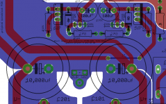


Dario, could you explain the flexibility in the range of values at C102 /202?
100uf/50V to 47uf/25V seems quite a spread.
The only important parameter is the voltage rating (25V and up), any capacitance between 47uF and 100uF will do.
Their only function is to ensure regulator stability but so far it seems to work perfectly also without them.
The RevC counterparts had the function to reduce ripple and impedance, this is not the FE case.
"Inviato dal mio LG-P500 usando Tapatalk " ???
Glad to hear of your new phone. Google Translate relieved my fear that you were swearing at me
My smartphone is over a year old... simply this time I've answered from bed (it was 1:30AM and I was trying to fall asleep...)
I've checked Mouser's shared BOM and it includes caps (Nichicon FW) for C102/C202 but in this moment they're not available, maybe this is the reason you didn't received them, Bob.
BTW It could be better this way, they're not so good for those positions, final BOM will have different caps (probably FG: 647-UFG1H101MPM)
Cerafines are very good caps for those position.
BTW It could be better this way, they're not so good for those positions, final BOM will have different caps (probably FG: 647-UFG1H101MPM)
Cerafines are very good caps for those position.
Thanks, I found some 100uf / 50V from the MyRef 1.3/1.2 builds. I'll add something better to my next order.
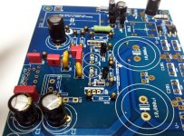
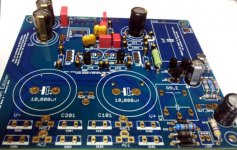
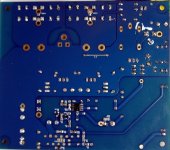
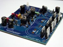
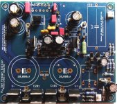
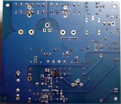
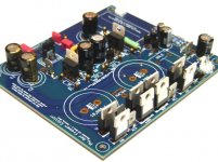
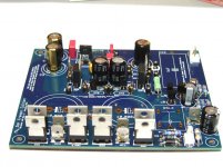
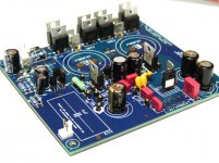
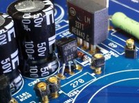
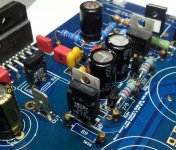
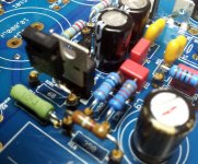
Here are the pics of all installed other than Heat Sinks, Relay. LM3886 (I think)
Please review.
FE-1
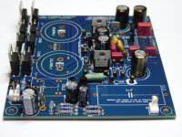
Here are the pics of all installed other than Heat Sinks, Relay. LM3886 (I think)
Please review.
FE-1
Attachments
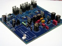
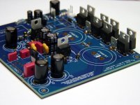
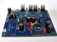
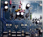
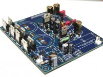
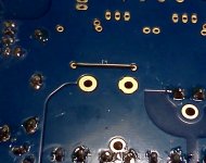
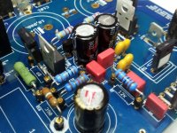
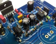
Just found a mistake 

I mounted and trimmed R3 before attaching the heat sink so now the leads are too short. I remember one must do this with the LM3886 chips but I totally forgot it on R3. Luckily I have some double sided CPU heat transfer tape I can use till I get some new parts
I mounted and trimmed R3 before attaching the heat sink so now the leads are too short. I remember one must do this with the LM3886 chips but I totally forgot it on R3. Luckily I have some double sided CPU heat transfer tape I can use till I get some new parts
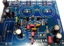
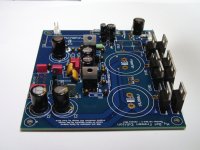
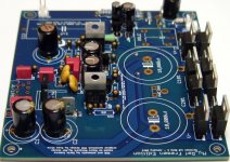
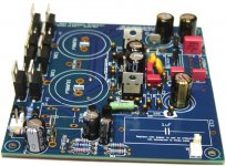
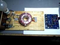
Just one note on transformer wiring, since I didn't wrote anything about it.
The transformer should have double 25V (24V also fine) secondaries, let's say:
Secondary 1: green/yellow
Secondary 2: violet/white
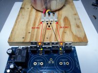
They should be branched that way:
Green to AC1, Yellow to NAC1
Violet to AC2, White to NAC2
Please confirm.
Attachments
- Status
- This old topic is closed. If you want to reopen this topic, contact a moderator using the "Report Post" button.
- Home
- Amplifiers
- Chip Amps
- My_Ref Fremen Edition - Beta build/Fine tuning