I think the 1 refers to capacitance
The M refers to metalised
The K refers to film
The last letter if shown usually refers to the type of film.
Thanks Andrew. It's very interesting. That may be a more clear format for labeling capacitors than we use.
Jac
1 MK(Greek letter Phi) = 1uF
That letter looking like a greek Phi is infact F in russian alphabet so you have 1mkf. Russians write everything like they hear.
Greetings from Bucharest")
Thanks Atupi. Greeting to you from the Michigan countryside. I hear Bucharest is beautiful.
You information is even more interesting. Aren't the differences between cultures amazing?
Dario,
Thanks for the point on poly styrene caps and their temperature sensitivity.
Andrew,
Thanks for the soldering tips on the polystyrene caps. I look for some of those heatsinks too. They sound like a great tool and who doesn't love buying tools.
Since I had planned on some cap comparison of my own and an evolution from single ended to balanced, I may try mechanical connection until I get to what I think is final.
There is a philosophical question for us. Is any project every finished for a DIY person?
Boy, am I in over my head !
Thought it would be a fun challenge where I might learn something, but between the gerbbers, schematics and renderings, what I figured out was my need to do a whole lot more reading and study.
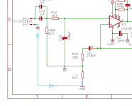
I did see what I think soongsc is refering to with R11. The blue path can't be completed because R11 performs "Groundes Interruptus". Correct?
Don't know if I'll ever have the time and brain power to catch up to you tech types.
Thought it would be a fun challenge where I might learn something, but between the gerbbers, schematics and renderings, what I figured out was my need to do a whole lot more reading and study.
I did see what I think soongsc is refering to with R11. The blue path can't be completed because R11 performs "Groundes Interruptus". Correct?
Don't know if I'll ever have the time and brain power to catch up to you tech types.
Attachments
Boy, am I in over my head !
Thought it would be a fun challenge where I might learn something, but between the gerbbers, schematics and renderings, what I figured out was my need to do a whole lot more reading and study.
Bob,
You can't be too far behind because I can see you from where I am. I guess that just means I'm not a tech type either. Anyway, we keep learning. That's part of the fun.
If you want an easy to use, but somewhat limited tool for playing with circuit simulations on-line, check out Circuit Lab. It has been useful to me, even though I have more professional (complicated) tools
https://www.circuitlab.com/
Boy, am I in over my head !
That is just what I thought when I looked at the very clean and tidy board pictures you posted Bob.
I have been quietly worrying about doing a good job of soldering all the tiny smd components in this project.
Somewhere I saw a link to this video which is helpful.
Surface Mount Soldering 101 Video
The recommended iron temp 610 deg F being close to 320 deg C.
Any more good advice from the wise? Good tips for holding the small parts in place while soldering?
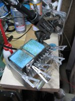
Andrew mentioned heat sinks for soldering heat sensitive capacitors, I keep mine clipped to the fins of an old heat sink, they cool down really quickly after use. Bench is getting messy eh!
Bill
Attachments
I have been quietly worrying about doing a good job of soldering all the tiny smd components in this project.
(...)
Any more good advice from the wise? Good tips for holding the small parts in place while soldering?
Hi Bill
dont' worry about SMD soldering, all components are big (for SMD standards) and can be easily handled with twezers.
To solder them all you need is:
- your soldering iron
- tweezers
- tacky flux (Mouser 910-SMD291)
- thin solder alloy (0.5mm diameter)
- you apply the tacky flux to pads
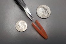
- You remove the component from their package (a cutter can be useful to detach the film that close it)
- Using tweezers you place the component on 'fluxed' pads (take care to orientation)
- (the flux will help in keeping the part in place)
- wet the iron point
- while keeping the component in place with tweezers touch one of the pads (and part) with the iron
- (thanks to the flux a thin film of solder will quickly fix the component)
- apply solder (only a tiny bit!) on the other pad (it will be easy since the component is already fixed in place by other pad)
- if you think you'll need it apply some more solder to the first pad.
Then keep it in place with tweezers and solder two opposite pins (like 1 and 5) now that the component is fixed you can proceed easily with other pins.
You don't need to apply solder directly, just wet the point for each pin.
Start from the pin and go outside on the pad.
Last edited:
Fear not Bill. The placement of the surface mount chip are very accessible. I think everyone is going to find it a lot easier than anticipated.
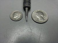
This is all I have ever used and it's been just fine.
Stahl Tools SSVT Variable Temperature Soldering Station 374-100
The tip came with the station and has a replacement package identical to the one included.
Stahl Tools SSRT 4-Piece Soldering Tip Kit for STSSVT 374-102
Tweezers came from my local CVS drugstore.
I use something similar to this and a copper chore-boy from the grocery store. Once you tin a pad on the BCB you will have 90% of the skills needed. Dario's boards are top quality and rugged. You won't have a problem.
I learned what I know from the same video. It's excellent!
Of course if you don't already have one, a big unit like this is wonderful. I got mine on sale for $19
Attachments
Last edited:

Dario, I'll audition the Amtrans tomorrow. I changed today's priorities to home-made bean soup with ham and bacon and thick sourdough Italian bread. You know what happens when something gets in you head.
No problem...
when polystyrene caps are damaged, can they still maintain their value while losing the
ability to block dc? im thinking the relay issue i have with one channel is due to the 22uf k71-4 cap in speaker relay circuit being damaged from too much desoldering.
Why don't you just try to replace it with a elco, then?
i just got done doing the r10<->c9 mod and i can't really comment on anything... because at the same time i swapped out 220uf blackgate std for 470uf nx.
everything's an improvement for certain-firmer bass and that 'veil lift' effect is most noticeable.
i'd like to know, though, if those who have had proper opportunity to a/b the swap mod had the chance to consider the effect on harmonics- does the mod decrease the richness of the sound in any way.
i can't really comment on whether the harmonics have intensified before the mod because i hadn't listened to the amp for two weeks before soldering it today. work is eating up my hobby...
everything's an improvement for certain-firmer bass and that 'veil lift' effect is most noticeable.
i'd like to know, though, if those who have had proper opportunity to a/b the swap mod had the chance to consider the effect on harmonics- does the mod decrease the richness of the sound in any way.
i can't really comment on whether the harmonics have intensified before the mod because i hadn't listened to the amp for two weeks before soldering it today.
work is eating up my hobby...
Last edited:
so the curiosity got the better side of me and i risked my boards to heat destruction once more... with c9 r10 back in their respectable places, there's more depth to sound stage, more air n a bit more warmth in trade off to bass and instrument separation.
for the lack of better term,
c9 r10
original position -> more tubey
swapped -> more hifi
i'm not advocating one over the other- for both sound excellent and on par in overall score. for me though, original position has more romance to music.
for the lack of better term,
c9 r10
original position -> more tubey
swapped -> more hifi
i'm not advocating one over the other- for both sound excellent and on par in overall score. for me though, original position has more romance to music.
- Status
- This old topic is closed. If you want to reopen this topic, contact a moderator using the "Report Post" button.
- Home
- Amplifiers
- Chip Amps
- My_Ref Fremen Edition - Beta build/Fine tuning