It's not a case of "seems resonable".
One should be asking questions along the lines of:
Why do I need a Zener there?
If I adopt a Zener, then what benefits can it bring?
Which parameters will deliver those benefits?
What operating conditions will enable those parameters?
Will some other device bring with it better benefits with fewer (or lesser) compromises that the Zener requires?
Simply swapping one device for another is guessing.
It's not exactly so...
In fact I've tried those 1N53xx because Siva recommends them as much better sounding ones (and in My_Ref stock supply is so).
I've also though about it and in a mail to Siva (1.16.2012) I wrote him:
You suggested the use of 1N53xx zeners and as you know I've included them in the BOM for the Fremen Edition but, since I'm ordering components for the beta build, I've some doubt about them, i.e. did you adjusted R1 and R4 value to use them?
From the datasheet I see that BZX85 works at Izt=20ma while 1N53xx with Izt=100ma, shouldn't the current be adjusted to suit that?
Siva reassured me that they would work also at much lower currents, though not specifying how much lower.
Last edited:
Sorry for the late answer...
The shunt is nearly identical to ESP project 37's PS:
(Image linked from ESP' site)
The simpler shunt can be found here, the one I'm using adds the base/emitter resistance, which acts as a sort of feeedbak (terminology may be not proper).
A nice thread to read, where another very similar design is referenced.
Another reference is AN58 from Zetex (using TL-431)
The transistor lowers zener's output impedance by transistor's HFE, isn't it a nice thing to have?")
BTW it sounds better with than without...
Looked at the schematic. It's not exactly a simple shunt, we need to consider how it biases the transistor. I think this is what Andrew was suggesting.
The shunt is nearly identical to ESP project 37's PS:
An externally hosted image should be here but it was not working when we last tested it.
(Image linked from ESP' site)
The simpler shunt can be found here, the one I'm using adds the base/emitter resistance, which acts as a sort of feeedbak (terminology may be not proper).
A nice thread to read, where another very similar design is referenced.
Another reference is AN58 from Zetex (using TL-431)
Now that I look at it, do we really need the transistor?
The transistor lowers zener's output impedance by transistor's HFE, isn't it a nice thing to have?
BTW it sounds better with than without...
I have not done the calculation, but if the total current sink is always within the limit of the device it is supplied to, then it is fine. However, since we are only redirecting current based on the variation of load impedance. The source impedance should remain high. I tend to think that the design should be geared towards damping of current.
I have not done the calculation, but if the total current sink is always within the limit of the device it is supplied to, then it is fine. However, since we are only redirecting current based on the variation of load impedance. The source impedance should remain high. I tend to think that the design should be geared towards damping of current.
I don't understand... can you elaborate?
BTW
According to datasheet LM318's maximum supply current is 10mA (5mA typical).
The CCS generates 24.5mA, the zener current (basically set by the 200R resistor) should be 3.2mA so, current flowing through transistor is between 11.3mA and 16.3mA according to the opamp absorption.
It's pretty much the same concern as the total MyRef type design, damping. It's possible to do a sim of the PS design the same way you sim the MyRef circuit. For a CCS, the idle current plus the current sink must add up to what CCS provides. I don't know of a good way to elaborate on it, the only way is to just to a sim, which is something I will probably do when I get around to this board.
Last edited:
Hello guys,
Sorry for jumping into your thread but I've been reading your work for a while and I hope I can help. After drawing the circuit from ESP into Multisim and simulating it a bit I might have found answers to some of your questions.
First, do you use a 1W zener or a 5W ? Using a 5W limited by a R4 of 200R is far too low current. Using a 1N5363B, Izt is @ 40mA and Izm @ 158mA. According to my simulation, it starts to regulate properly @ 15mA so 47R would be appropriate. Using a 1W zener, 100R is perfect and to simplify everything you should stick to a 1W. And yes 1N53xx is simulating better than many other zeners so they might be better sounding too.
Second, simulating the circuit, I get around 3.45uV RMS(1N5363B), but if I add an other 2200uF capacitor after R2 in parallel of C3, the ripple drops to 1.94uV RMS(1N5363B). It makes a 2 stage RC filter and seems to work properly.
It's up to you to take the risk of using a better sounding zener but according to my simulation, improving the RC filter is reducing the ripple by as much as using a better zener. Sure you can risk everything and do both.
Sorry for jumping into your thread but I've been reading your work for a while and I hope I can help. After drawing the circuit from ESP into Multisim and simulating it a bit I might have found answers to some of your questions.
The CCS generates 24.5mA, the zener current (basically set by the 200R resistor) should be 3.2mA so, current flowing through transistor is between 11.3mA and 16.3mA according to the opamp absorption.
First, do you use a 1W zener or a 5W ? Using a 5W limited by a R4 of 200R is far too low current. Using a 1N5363B, Izt is @ 40mA and Izm @ 158mA. According to my simulation, it starts to regulate properly @ 15mA so 47R would be appropriate. Using a 1W zener, 100R is perfect and to simplify everything you should stick to a 1W. And yes 1N53xx is simulating better than many other zeners so they might be better sounding too.
Second, simulating the circuit, I get around 3.45uV RMS(1N5363B), but if I add an other 2200uF capacitor after R2 in parallel of C3, the ripple drops to 1.94uV RMS(1N5363B). It makes a 2 stage RC filter and seems to work properly.
It's up to you to take the risk of using a better sounding zener but according to my simulation, improving the RC filter is reducing the ripple by as much as using a better zener. Sure you can risk everything and do both.
Sorry for jumping into your thread but I've been reading your work for a while and I hope I can help.
Sure you can, it's a very useful and informative post.
Thanks
After drawing the circuit from ESP into Multisim and simulating it a bit I might have found answers to some of your questions.
Wow, fantastic!
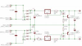
If your're willng to you should simulate the actual circuit:
But with the new values:
R101/R201=50R
R104/R204=200R
First, do you use a 1W zener or a 5W ? Using a 5W limited by a R4 of 200R is far too low current.
...
And yes 1N53xx is simulating better than many other zeners so they might be better sounding too.
I know...now...
In fact with BZX85 the 200R value works very well and I'm planning to use 1/2W 1N5244B zeners so that the 3.2mA would be plenty for them.
I think 1/2 watt should be good... 3.2mA * 14V gives less than 50mW, ten times less than rated dissipation.
If I raise CCS' current output heatsinking became necessary and there no space for it on the PCB.
Second, simulating the circuit, I get around 3.45uV RMS(1N5363B), but if I add an other 2200uF capacitor after R2 in parallel of C3, the ripple drops to 1.94uV RMS(1N5363B). It makes a 2 stage RC filter and seems to work properly.
This is for the ESP circuit... my PS, without the pi-filter, could have more ripple but I can't say for sure, the CCS (not present on ESP circuit) should help a lot in that regard.
Attachments
This is for the ESP circuit... my PS, without the pi-filter, could have more ripple but I can't say for sure, the CCS (not present on ESP circuit) should help a lot in that regard.
Just started simulating yours. ESP's circuit is a nice 120Hz sine wave @ 10.2uV pk-pk... The LM317 introduces an irregular sawtooth waveform of 175nV pk-pk using the 1N5244B and 320nVpk-pk using the BZX85C13.
I'll post better measurements later...
Just started simulating yours. ESP's circuit is a nice 120Hz sine wave @ 10.2uV pk-pk... The LM317 introduces an irregular sawtooth waveform of 175nV pk-pk using the 1N5244B and 320nVpk-pk using the BZX85C13.
Interesting... so ripple is much lower but of worse quality, right?
I need to add a LM318 to my simulation to be sure. The op amp might reject a lot of noise so improving the circuit might give no result. Sine and sawtooth might affect the LM318 the same way (It's getting too much theoretical). Sometimes balancing imperfect variables sounds better...
The original RevC has the same kind of sawtooth ripple but it is more in the range of 25uV pk-pk. The diode might be the cause of the sawtooth (and not the LM317).
One thing is sure, the 1N5244B simulates better than the BZX85C13 in your circuit.
The original RevC has the same kind of sawtooth ripple but it is more in the range of 25uV pk-pk. The diode might be the cause of the sawtooth (and not the LM317).
One thing is sure, the 1N5244B simulates better than the BZX85C13 in your circuit.
Some models don't properly implement models to simulate power supply loading. Just need to be sure what kind of models are used. Probably just using a current source to look at how stable the power supply is would be good enough. If improvements do now show up in listening, then we can say the PS design had reach a point where no further modification will help.
I don't understand... can you elaborate?
BTW
According to datasheet LM318's maximum supply current is 10mA (5mA typical).
The CCS generates 24.5mA, the zener current (basically set by the 200R resistor) should be 3.2mA so, current flowing through transistor is between 11.3mA and 16.3mA according to the opamp absorption.
I think your CCS is generating more current than you think. Please look at the bottom of this page.
Amplifier topologies for current-drive - Current-Driving of Loudspeakers
I think your CCS is generating more current than you think. Please look at the bottom of this page.
I don't think so:
(image linked from current-drive.info)
The CCSs used int he PS are type (a), according to the article the current is always VRef/R.
In case (c) current would be higher as you told but it's not our case, am I wrong?
- Status
- This old topic is closed. If you want to reopen this topic, contact a moderator using the "Report Post" button.
- Home
- Amplifiers
- Chip Amps
- My_Ref Fremen Edition - Beta build/Fine tuning