That's a typical symptom of either a dry (non-ohmic) joint on one of the resistor leads, or a flaky resistor with a cracked/loose/non-ohmic end-contact. Reversing it probably fixed the dry joint or made the end-contact sit snugly, thus solving the problem
Hi Siva,
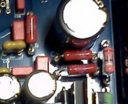
all through hole signal resistors are socketed (see attached magnification) so the difference is not soldering related.
I've reversed it several times with always the same results.
Takman REX, in my experience, are directional.
The Same for PRPs.
It could also account for some of the hum/crackling artefacts reported - in my experience, the MyRef is sensitive to dry joints at several location
This is a possible hint, maybe the problem is socket related...

Attachments
Does it make sense to put two in opposite directions to make the result non-directional?Hi Siva,
all through hole signal resistors are socketed (see attached magnification) so the difference is not soldering related.
I've reversed it several times with always the same results.
Takman REX, in my experience, are directional.
The Same for PRPs.
This is a possible hint, maybe the problem is socket related...

Does it make sense to put two in opposite directions to make the result non-directional?
Maybe...
I think that I've finally found where is the problem... LM317's power dissipation.
When idle temperature on LM337 is 44 °C, on LM317 57°C (23°C room temperature).
I've replaced both LM317, the new ones heatsinked, problem seems gone.
What puzzles me is that when on breadboard this problem did not appear.
Just for the sake of precision I've measured also both unregulated rails (+33,6Vdc and -34Vdc with 2x24Vac transformers) so there is not a voltage difference...
So for all beta builders: buy TO-220 thin heatsinks for LM317s
This Mouser code should be suitable: 532-576802B00
Attachments
Last edited:
what changed ?What puzzles me is that when on breadboard this problem did not appear
How many 68R and 270R should one buy to get a good match ? ... or can I pay PartsConnexion to match for me ?
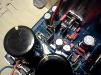
Interesting heat sink on your 3886.
Are the Mundorf smoothing caps bigger (taller) than Panasonic TS-HA 50V at C101.201 ? Your M-Lytic are 10000uf 63V MLGO right. I think the chassis I am working on is too small.
what changed ?
Maybe the fact that on breadboard there were more air around them... I don't know.
How many 68R and 270R should one buy to get a good match ? ... or can I pay PartsConnexion to match for me ?
Interesting heat sink on your 3886.
I don't think matching is necessary with 1% resistors.
The 'heatsinks' are server heatsinks for harddisks... temporary, obviously...
Are the Mundorf smoothing caps bigger (taller) than Panasonic TS-HA 50V at C101.201 ? Your M-Lytic are 10000uf 63V MLGO right. I think the chassis I am working on is too small.
They're both 50mm tall.
How would you describe the sonic difference compared against your original breadboard mods? Is there anything about the sound that specifically catches your attention?Maybe...
I think that I've finally found where is the problem... LM317's power dissipation.
When idle temperature on LM337 is 44 °C, on LM317 57°C (23°C room temperature).
I've replaced both LM317, the new ones heatsinked, problem seems gone.
What puzzles me is that when on breadboard this problem did not appear.
Just for the sake of precision I've measured also both unregulated rails (+33,6Vdc and -34Vdc with 2x24Vac transformers) so there is not a voltage difference...
So for all beta builders: buy TO-220 thin heatsinks for LM317s
This Mouser code should be suitable: 532-576802B00
Is there anything about the sound that specifically catches your attention?
It's like a sort of ringing/distortion that occasionally comes out on level variations.
I think the problem is not PCB related but to the fact that the PS components, probably, don't like the resistor swapping and get damaged.
Just to be sure that it's not related to the amp section I've pulled out the entire PS and mounted the stock My_Ref PS, it sounds perfect.
After that I've mounted again the shunt transistors and resistors, it seems to sound perfect (but better
) too.I've run out of LM317/LM337, in the next days I'll remount also them.
Now that I have all components I've mounted also the voltage limiter, it seems it has no adverse effects.
Going on
Today, I've mounted 14V BOM's zeners and so far it continues to sound good.
Just a note: while 1N53xx sounds fuller they, maybe have a touch of hardness but as hours are passing it seems to lower.
According to tracking packages left Italy this friday so I think that between the end of the next week and the beginning of the next should arrive at beta testers' home.
You can solder the pins on the PCB to avoid slaughtering of the card
If you're referring to sockets for easy swapping of components I do already use them
Power Supply for the LM318
Where did you get the design of the +-14 volt power supply?
The LM317 and LM337 voltage regulators state that they need a
minimum of 10mA in order to work correctly. Your current sources
are only putting out about 18mA of current each. The formula in the
data sheet is I(out) = 1.25V/R1 = 1.25V/68 Ohm = 18.38mA.
That's only about 8mA above the minimum. Did you try R1=50 ohms
or R1=25 Ohms?
In addition, why didn't you do the following for the power supply
design:
LM317 & LM337 LM317 & LM337
Voltage Regulator ---------> Second Voltage Regulator ---> To LM318
Did someone do a simulation of your design? A recent article in Nuts and Volts
Magazine stated that dual LM317 and LM337 is better than a single set
of positive and negative regulators.
Where is you get the remaining part of the LM318 power supply from
(the zener's, transistors, etc.)?
More about the LM318 Power supply
I'm not used to the editing tools on diyaudio.com. The suggestion for a
new power supply should be:
LM317&LM337 Volt.Reg Pair--->LM317&LM337 Volt Reg Pair---> LM318
In other words, two stages of LM317&LM337 in series. Each stage could
drop the voltage down a certain amount, thus each stage would drop 1/2
of the voltage. The output would still be +-14 Volts into the LM318 chip.
In addition, the LM317/LM337 data sheets state that a 10 microFarad capacitors
from the adjust pins to ground will reduce the ribble by about 15dB (see figure14 and 15) in the data sheet.
Maybe Linuxgurf cound simulate both designs to see which is best. Take care.
Measure the voltage accross the 68 Ohm resistors
This does not make sense, If the formula in the data sheet states the the output
current is 1.25V/R1 then there should only be 18.38 mA going thru each voltage
regulator. With a drop of =voltage from say 28Volts input to 14 volts output, that
a delta v of 14 volts, Power = IV = 18.38mA * 14 V = 0.2574 watts
That's why we need to know the voltage drop across each of the 68 Ohm
resistors to determine that exact current flow. Take care.
Maybe...
I think that I've finally found where is the problem... LM317's power dissipation.
When idle temperature on LM337 is 44 °C, on LM317 57°C (23°C room temperature).
I've replaced both LM317, the new ones heatsinked, problem seems gone.
What puzzles me is that when on breadboard this problem did not appear.
Just for the sake of precision I've measured also both unregulated rails (+33,6Vdc and -34Vdc with 2x24Vac transformers) so there is not a voltage difference...
So for all beta builders: buy TO-220 thin heatsinks for LM317s
This Mouser code should be suitable: 532-576802B00
This does not make sense, If the formula in the data sheet states the the output
current is 1.25V/R1 then there should only be 18.38 mA going thru each voltage
regulator. With a drop of =voltage from say 28Volts input to 14 volts output, that
a delta v of 14 volts, Power = IV = 18.38mA * 14 V = 0.2574 watts
That's why we need to know the voltage drop across each of the 68 Ohm
resistors to determine that exact current flow. Take care.
Where did you get the design of the +-14 volt power supply?
Basically is a pretty standard shunt regulated design with LM3x7 CCS.
There is plenty of similar circuits on the net.
The LM317 and LM337 voltage regulators state that they need a
minimum of 10mA in order to work correctly.
...
Did you try R1=50 ohms
or R1=25 Ohms?
You're right, in fact the actual recommended value is 50R
In addition, why didn't you do the following for the power supply
design:
LM317 & LM337 LM317 & LM337
Voltage Regulator ---------> Second Voltage Regulator ---> To LM318
While I'm sure the double stage regulator approach sounds better than a single stage one with LM3x7s I think the zener/transistor shunt sounds better.
In my tests the difference between a single stage LM3x7s PS vs the zener/transistor shunt (without CCS!) was pretty obvious.
This does not make sense,
...
Power = IV = 18.38mA * 14 V = 0.2574 watts
I do agree, when the new LM3x7 will arrive I'll measure and compare again.
Probably the different temperature was due to a faulty BC639/BC640
Last edited:
Breadboard problems
Quote:
What puzzles me is that when on breadboard this problem did not appear.
Remember that a breadboard is basically plates separated by plastic dielectric
material. Hence, breadboards have a lot of built in capacitance.
I would suggest placing four capacitors around the LM317 and LM337. The
input capacitors would be 0.1 microfarad. The output would be 1.0 microfarad.
The data sheet says use high quality tantalum. Try this before you replace the
voltage regulators. They could be oscillating, hence, that high temperatures. Take\
care.
Remember that a breadboard is basically plates separated by plastic dielectric material. Hence, breadboards have a lot of built in capacitance.
Interesting, never though about it.
I would suggest placing four capacitors around the LM317 and LM337. The input capacitors would be 0.1 microfarad. The output would be 1.0 microfarad.
Both datasheet and this Jung's article don't talk about decoupling for LM3x7 CCSs...
They could be oscillating, hence, that high temperatures.
Or simply a broken BC639 lower output voltage and thus raise voltage on LM317, paired with same current -> higher temperature.
In these days, waiting for the LM3x7s to arrive, I've made several measurements and experiments.
For example measuring currents with a multimeter leads immediately to a broken BC639/BC640 AKA lower output voltage.
Just a note: while 1N53xx sounds fuller they, maybe have a touch of hardness but as hours are passing it seems to lower.
That hardness never gone completely while BZX85 didn't have it.
Superfigone pointed out via email than he thought the 270R don't give enough current to flow through the zener.
In fact, since Vbe measures 0.638V, current is 2.36ma.
So I've tried 200R (current = 3.19mA) and hardness seems almost gone.
Probably 150R (4.25mA) could be better.
I did expected to fine tune values but I didn't expected that the initial values could be bad....
Zeners are generally run where they are on the low dynamic impedance part of the I vs V curve.
If you run too low a current through the Zener you can be operating off the low dynamic impedance part of the curve.
I recommend that any Zener be run at 10% to 99% of it's max operating Power dissipation.
If you run too low a current through the Zener you can be operating off the low dynamic impedance part of the curve.
I recommend that any Zener be run at 10% to 99% of it's max operating Power dissipation.
I recommend that any Zener be run at 10% to 99% of it's max operating Power dissipation.
Incredible, I was just reading some docs on dimensioning zener shunt regs... same recommendation.
Andrew, are you remote-controlling my mind?
Jokes apart, so it seems the 1N5352 should be operated at about 32mA...
In 1N53xx datasheet I can't find any indication on minimum zener current while on BZX85 one is clearly stated that minimum current is 2.7mA, quite lower than the 7mA found using the rule of thumb.
But even if we suppose that 1N53xx behaves in the same way (no guarantee about that) we still need at least 20mA...
Maybe going back to BZX85s could be wiser... I don't know...
- Status
- This old topic is closed. If you want to reopen this topic, contact a moderator using the "Report Post" button.
- Home
- Amplifiers
- Chip Amps
- My_Ref Fremen Edition - Beta build/Fine tuning