Illusus, wether you are skilled or not check allways the datasheet and application notes. There you have all info for using the IC. If you don't understand some parts we will happily help you.
http://www.national.com/an/AN/AN-1192.pdf
http://www.national.com/ds.cgi/LM/LM3875.pdf
I know my post is rather boring but National happens to have one of the best datasheets and application notes, very much worth reading.
http://www.national.com/an/AN/AN-1192.pdf
http://www.national.com/ds.cgi/LM/LM3875.pdf
I know my post is rather boring but National happens to have one of the best datasheets and application notes, very much worth reading.
Nuuk said:It should do.
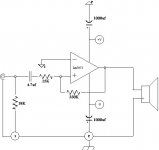
it couldn't have worked, as the inputs are swapped.
it seems that you wanted an inverting topology but with different resistor values. the resistor values will work, but the topology will not.
Besides swapping inverting and noninverting inputs, and setting it up for large DC offset by not compensating for bias current, you've also got a situation where disconnecting the speaker could remove the input ground reference.
Bad circuit all around. Use the app notes as P-A suggests. Those National guys are pretty smart and actually know how to use their chip.
Bad circuit all around. Use the app notes as P-A suggests. Those National guys are pretty smart and actually know how to use their chip.
Oh my... inversed input is just a typo, thanks for pointing it out, I may have followed it during construction. With that reversed, do all the values look good? 
I have read the national sheet, it's not that boring") . I ask because I just want to make sure everything is ok, I'm very unsure of my "skill". Someone once told me there are no stupid questions, I hope he didn't say that to make me look stupid.
. I ask because I just want to make sure everything is ok, I'm very unsure of my "skill". Someone once told me there are no stupid questions, I hope he didn't say that to make me look stupid.
The reason I decided to compile a couple of suggestions before I start is because it seems that on every "look at my igc" thread the changes I included now, are suggestions.
I have been reading entry level elctronics text books and plan on taking some night classes as I become more and more interested. I am starting to understand schematics not just copy them. I still don't understand much but I do get excited when I look at a simple cuircuit and can follow it. It feels good knowing which component does what, I do have a problem with how much it does of what it's doing (values)....so bear with me guys one day I may even have some noteworthy input not just annoying questions.
I have read the national sheet, it's not that boring
. I ask because I just want to make sure everything is ok, I'm very unsure of my "skill". Someone once told me there are no stupid questions, I hope he didn't say that to make me look stupid.The reason I decided to compile a couple of suggestions before I start is because it seems that on every "look at my igc" thread the changes I included now, are suggestions.
I have been reading entry level elctronics text books and plan on taking some night classes as I become more and more interested. I am starting to understand schematics not just copy them. I still don't understand much but I do get excited when I look at a simple cuircuit and can follow it. It feels good knowing which component does what, I do have a problem with how much it does of what it's doing (values)....so bear with me guys one day I may even have some noteworthy input not just annoying questions.
it couldn't have worked, as the inputs are swapped.
I didn't check the inputs but I think that was more of a typo than anything. Still, as you guys point out - it would not work that way round.
I do agree that for anyone starting out, it is best to stick with a proven circuit.
Illusus said:Oh my... inversed input is just a typo, thanks for pointing it out, I may have followed it during construction. With that reversed, do all the values look good?
it will work if you correct the input error.
The chip is surprisingly fault-tolerant. I ran it with just two resistors and it worked flawlessly. I used much lower resistors (20k/1k combo) because that's what I had. No problem whatsoever. The key here is the ratio between the two, not their absolute value.
There is no reason that yours wouldn't.
Illusus...you are off to a start with a design and asked questions......dont feel bad about that as we all make mistakes in venturing into new things .....your other design criteria should be your input to this amplifier as you have used a low impedance so now you should look at what source will be providing the signal and whether it is suitable or else you will need to adjust the input impedance of your design
just food for thought....keep up the good work!!!
DIRT®
just food for thought....keep up the good work!!!
DIRT®
- Status
- This old topic is closed. If you want to reopen this topic, contact a moderator using the "Report Post" button.
- Home
- Amplifiers
- Chip Amps
- Does this make sense?