Here's the story. I ordered some LM3875TF samples from National and got Panasonic FC 1000uF/50V caps, Takman carbon film resistors (22k and 680 Ohm), a 250VA 2x22V transformer and a perforated board on which I hooked it all up. It didn't look like much being basically point to point wired and attached to a cpu cooler. But it played wonderful. It could play mp3 of a normal PC output like nothing I heard before... I had to mess it up
Since there was a noise when turning it on, and when I turned it off after ~20 sec there was a noise again. Nothing a better grounding scheme wouldn't cure. So I decided to order a set of PCBs from a eBay seller called audiosector (NOT to be mistaken for Peter Daniel) from NY.
I used the exact same components (unsoldered them from my amp) and put them on the PCB. The magic is gone, and no matter what I do I can't get it back and I tried bypass caps (WIMA MKP10 0.1uF)...ended up using the pcb only for the power supply and soldered the resistors point to point. It works good, but not like the first one and I keep having a feeling that all is not well. There is some white noise when I put my ear near the tweeter but it doesn't seem to be too much.
The old one was warm and detailed with a large sound stage with a black background, and I listened to it for hours without fatigue
The new one is a bit harsh and I just don't want to listen to it as much
Guess I'll order Peters PCBs, I have a feeling that guy knows what he is doing.
Did anyone else have a similar experience, and more importantly, is there a cure?
P.S. I have two good systems with pretty much everything successfully modded, I used the PC with the mp3 just for testing..don't be hatin'
Last edited:
I would like to keep it a simple as posible, might try the zobel as the Gaincard uses it. I think you might be right about the oscillations, I keep having the feeling that something is wrong but I don't have the equipment to confirm that (I think Nelson Pass used similar words too in a paper about opamps). I used 0.1uF decoupling caps very close to the pins but that didn't seem to work.
I generated a 15kHz tone in Audacity and played it with the amp, I didn't get the clean tone I expected so that's what I'm looking at now. It had a sort of ring to it and that can't be right
I generated a 15kHz tone in Audacity and played it with the amp, I didn't get the clean tone I expected so that's what I'm looking at now. It had a sort of ring to it and that can't be right
My patience with the boards came to an end so I went back to point to point wiring and it seems it's working properly. The DC offset is lower about 20mV, the bass is back, the soundstage is back to center (it pulled to the right) and the instruments sound natural again.
I conclude that LM3875 is so simple to implement point to point that you shouldn't bother with the cheap eBay type PCB's
I conclude that LM3875 is so simple to implement point to point that you shouldn't bother with the cheap eBay type PCB's
My patience with the boards came to an end so I went back to point to point wiring and it seems it's working properly. The DC offset is lower about 20mV, the bass is back, the soundstage is back to center (it pulled to the right) and the instruments sound natural again.
I conclude that LM3875 is so simple to implement point to point that you shouldn't bother with the cheap eBay type PCB's
Congratulations, now We need pictures!!!
long time ago I build the LM3875 from Audiosector and it was very easy to build and with good results in the sound area. I was going to do it point to point, but I got scared and went for the easy way lol. I would suggest you to get a power supply at least 10.000uf per rail to achieve better bass. There are people that say small caps like 10uf, 47uf will sound better...When I build mine long time ago I try many values and from my own experience more capacitance will give more bass and it will not spoil sound.
I agree with Lanchile, these are quite the performer with a little capacitance.
I have not tried P2P with the LM3875, I find your statements interesting, might have to try it myself.
Here is my Peter Daniels boards on the breadboard. I might try some bypass caps, but it is more or less ready to go into a chassis. 23,500uf per rail, 94,000uf total. The extra capacitance really lit this focker up!
I don't think I lost anything at all in "quality". If I did lose a bit of quality for actual bass, it was a good trade IMO.
I did try snubbers on the rectifier, I didn't like it as much so took them off.
I like this amp so much it derailed my Bryston restoration. Blasphemy. I was then going to put the chipamp in the Bryston chassis, but I kinda like making the chassis so I'm unsure at the moment.
Attachments
As I understand it, a lot of capacitance in the filter is better but only if you parallel more smaller caps, a big cap of 10000uF has a slower response time.
@lanchile - it's just a piece of plywood with some components attached to it")
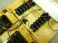
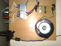
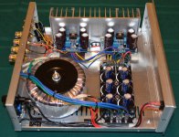
Hope I managed to attach the pics, this is a test setup connected to the computer, playing George Benson - Weekend in L.A. ('cause the music is why we make these amps, isn't it)
The white wires are made of a bunch small silver coated copper wires twisted together using a PC fan and some tape - it's an art form The white stuff is teflon tape.
@lanchile - it's just a piece of plywood with some components attached to it
Hope I managed to attach the pics, this is a test setup connected to the computer, playing George Benson - Weekend in L.A. ('cause the music is why we make these amps, isn't it)
The white wires are made of a bunch small silver coated copper wires twisted together using a PC fan and some tape - it's an art form
The white stuff is teflon tape.Attachments
As I understand it, a lot of capacitance in the filter is better but only if you parallel more smaller caps, a big cap of 10000uF has a slower response time.
@lanchile - it's just a piece of plywood with some components attached to it
Hope I managed to attach the pics, this is a test setup connected to the computer, playing George Benson - Weekend in L.A. ('cause the music is why we make these amps, isn't it)
The white wires are made of a bunch small silver coated copper wires twisted together using a PC fan and some tape - it's an art form
Try at least 6.800uf 105c X 2 per rail that will be 27.000uf total. More than 20.000uf per rail(40.000uf total)will not make a noticeable improvement.
Hi Mr.Vetz,
Did you followed the star grounding pattern, no matter either point-to-point or pcb? Did you seperated the input grounds from the output grounds? Where did you connected your speaker ground return wires? Is there any humming or buzzing sounds still? or it is damn silent even at the full volume?
Can you post the pic of your illfated pcb so i can see where and how the tracks are arranged?
And! Sorry for being late.
Thanks!
Last edited:
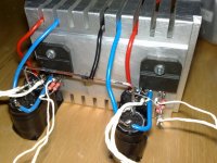
Star grounding is important if you don't want turn on/off thumps and hums of whatever. I followed the basic principles of this, separate signal ground conected via a small wire to the power ground, the speaker ground is dead center in each channels power ground, these grounds are connected by a heavier solid core wire like in Peter Daniels kit building instructions. The center of that solid core is connected to the PSU ground with the thickest wire I could find. This smaller to thicker wire arrangement is what cured the thumps for me.
The PCB doesn't discriminate between signal and power ground, I don't like this but the pics of the original gaincard I found on the web show a similar wiring.
btw. I put a ELNA Silmic II 22uF at the input and an extra 1000uF per PSU rail. I like the result.
here's da pic
The PCB doesn't discriminate between signal and power ground, I don't like this but the pics of the original gaincard I found on the web show a similar wiring.
btw. I put a ELNA Silmic II 22uF at the input and an extra 1000uF per PSU rail. I like the result.
here's da pic
Attachments
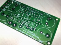
Yes! this pcb has certain serious grounding problems.
One of it has already been identified by you. Output ground should be seperate from the power ground. On the top it should never pass between the filter capacitors.
You can get much better pcbs or complete kits from Audiosector or you can directly contact to Mr.Peter here on diyaudio.com.He will certainly help you regarding this.
However, pcb's really sucks at some points. Specially, when we want to follow the star grounding patterns. 100% star grounding achievement is not possible with any pcb.
Vero Board works better for this. What about trying to build your project on a veroboard instead of ordering the pcb's before?
I think, this will help you: Audiosector LM3875.
Thanks.
Try at least 6.800uf 105c X 2 per rail that will be 27.000uf total. More than 20.000uf per rail(40.000uf total)will not make a noticeable improvement.
Just finished a LM1875 gainclone. I had ordered a board from China with 60,000 uF of capacitance. When it arrived, all six 10,000 uF caps proved fake, so I had to replace them with six 2,200 uF capacitors that I had laying around. The LM kits had an addition 2 x 1,000 uF caps right on board. So I have a total of about 8,800 uF per amp.
Question is, do I tear things up and kick those caps up to 4,700-6,600 uF for a noticeable gain in bass?
The amps seems to be quite fine now, but I do like extra bass when I can get it.
Attachments
So your at around 4400uf per rail per amp, I think you would hear an improvement with a little more. At least double that.
Even though it's a 20w chip, your still listening to similar sound levels as a person with a LM3875 etc, on a day to day basis.
Sorry, my typo (I am good at that), the chips are actually LM3875 not LM1875.
- Status
- This old topic is closed. If you want to reopen this topic, contact a moderator using the "Report Post" button.
- Home
- Amplifiers
- Chip Amps
- First LM3875 impressions