Hi,
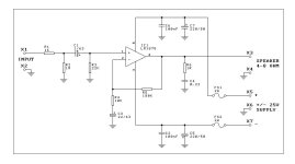
This is in refrence to the circuit diagram of LM1875 K50 kit.
I have certain confusions and questions regarding the schematic of K50 kit for LM1875, just out of the curosity to understand the diagram, much better and be able to redesign or choose the components value as according to my requirements and preferences.
1.What is the relation of R5(180K-feedback resistor) with R3(22k-Input impedance)?
2.Is there any relationship with C3(22uf) and R3(22k)? Both have the values 22uf and 22K. Is it mandatry to keep the values same? which means, if we keep the value of R3 as 47K, then we must keep the value of C3 as 47uf. similarly, 100K for R3 will go with 100uf of C3? or, we can keep the values, independent of each other, without causing any problem with the sound quality?
3. What if we want to keep the values of R3 as 100k and c3 as 100uf?How will this affect the sound quality? What values will go for other input components, if we keep R3 as 100K and C3 as 100uf so as to keep the same sound performance of the k50 kit?
4.Most of the line out signals from tape deck and some boomboxes are of the order of 4.7K output impedance. We know that the input impedance of the Amplifier should be at least 10 times greater than the output impedance of the source. So, if we want to connect the source with 4.7k as the output impedance, then we must have the input impedance of the amplifier as 47k(10 times of 4.7K) at least or greater. 22K(as with k50 kit) input impedance is not sufficient. What other components in k50 kit do i need to change if i changes the input impedance of 22k to 100K in LM1875 circuit?
5.What is the purpose of R2(1M). Do this resistance have any relation with R1 or any other component? Why only 1M? What if we increase or decrease R2?Will, this affect the input impedance in any way?
6.R1 also act as the atteunator for the signal input other than acting as a low pass filter in collaboration with 330pf(not shown) capacitor(parallel with R3) which also acts as the RF filter.What if we want to have more atteunation of the input signal to balance the overall gain of the amplifier, with respect to the input signal? How we will determine the exact value of the atteunator in such a scenario?
7.I want to use 100k volume pot. Which resistance can i replace with 100k volume potentiometer(R2(1M) or R3(22k))? and, how will this affect the other components in the circuit? How and what should i keep the values for other input components?
8.I want to use the active preamplifier at the input of LM1875, which acts as the Input source and has a DC filter capacor of 1uf at its output, along with the 1k resistance in series and 56 k in parallel at the output.
Its output impedance is say 4.7K. I can provide the service manual with schematic, for this active preamplifier, if anybody needs.
9.Thanks, to Mr. AndrewT for good explanation of "F-3db". where, C1(1uf) with R3(22k), acts as the High pass filter for blocking DC comming from the source input. Also, R1(1K) with 330pf(not shown) capacitor acts as a RF atteunator.This generates the bandwidth for LM1875 Amplifier.I will appreciate if he can help me with other confusions, as well.
10.Thanks, to Mr.Daniel for his wholehearted support and co-operation and to introduce me with LM1875 Amplifier.
Any helps offerred will be highly appreciated.
All suggestions are most welcome.
Thanks!
Attachments
Last edited:
On the K50 kit, R4 at 10k and R5 at 180k aren't really optimal and will make some distortion. That's far enough off that it is audible. So, that is too much sacrifice to support C3 at 22uF. So, we would want to proportionately increase the cap so we can decrease the resistor values. With R4 at 5k, R5 at 100k, C3 can be at 44uF and nearby values work. The R4 at 5k resistor value is still too high. Okay, so how about R4 at 2.5k (or nearby value), R5 at 50k (range 47k to 100k), and C3 at 100uF (or nearby value). The audible distortion is now gone from the K50 kit.
R6 should be more like 5 ohms and C4 should be 150nF (0.15uF) or a smaller figure.
If you wanted to install a potentiometer at your power amp, a simple thing to do would be to remove R1 and R2 and install your potentiometer at that location and that's simple because you're just replacing a fixed voltage divider with a rotary voltage divider.
You don't want to replace the R3 22k input load with a potentiometer since any momentary lapse of conductivity in the potentiometer would be fiercely loud noise.
R3 is your amplifier input impedance. This figure should be something that is useful to your source but not higher than R5. Of course, with a non-inverting amplifier, such as this one, R3 can be much lower than R5. For example, R3 at 22k would work. R3=R5 would work. And everything in-between would work. The amplifier has a generous tolerance to correct these differences but not quite enough for the folks at Quasar Kits.
And you want a different input load because of the needs of your preamp? The most you can do here is make input load resistor value = feedback resistor value for your power amp.
A bit of tug of war there? No problem.
R4 = 2.2k
C3=100uF (or 150uF)
R5 = 56k (or 62 or 68)
R3= 56k (or 52 or 47)
Install potentiometer at Input to preamp if it doesn't already have one.
P.S.
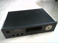
That Toshiba is just little preamp in a big box. If it were mine, I'd replace the transformer with a higher amperage model (also double check bridge rectifier current capacity) and then install one of the tripath amplifiers plus speaker jacks, as there seems to be plenty of space. If there was a voltage difference, it should be easy to run the preamp or power amp from a voltage regulator. The TA2020 is a single rail bridge amp with fairly wide voltage tolerance. Check out this datasheet: http://www.datasheetcatalog.org/datasheets2/30/300679_1.pdf
R6 should be more like 5 ohms and C4 should be 150nF (0.15uF) or a smaller figure.
If you wanted to install a potentiometer at your power amp, a simple thing to do would be to remove R1 and R2 and install your potentiometer at that location and that's simple because you're just replacing a fixed voltage divider with a rotary voltage divider.
You don't want to replace the R3 22k input load with a potentiometer since any momentary lapse of conductivity in the potentiometer would be fiercely loud noise.
R3 is your amplifier input impedance. This figure should be something that is useful to your source but not higher than R5. Of course, with a non-inverting amplifier, such as this one, R3 can be much lower than R5. For example, R3 at 22k would work. R3=R5 would work. And everything in-between would work. The amplifier has a generous tolerance to correct these differences but not quite enough for the folks at Quasar Kits.
And you want a different input load because of the needs of your preamp? The most you can do here is make input load resistor value = feedback resistor value for your power amp.
A bit of tug of war there? No problem.
R4 = 2.2k
C3=100uF (or 150uF)
R5 = 56k (or 62 or 68)
R3= 56k (or 52 or 47)
Install potentiometer at Input to preamp if it doesn't already have one.
P.S.
That Toshiba is just little preamp in a big box. If it were mine, I'd replace the transformer with a higher amperage model (also double check bridge rectifier current capacity) and then install one of the tripath amplifiers plus speaker jacks, as there seems to be plenty of space. If there was a voltage difference, it should be easy to run the preamp or power amp from a voltage regulator. The TA2020 is a single rail bridge amp with fairly wide voltage tolerance. Check out this datasheet: http://www.datasheetcatalog.org/datasheets2/30/300679_1.pdf
Last edited:
Their relation determines the output DC offset. In theory you want those resistors to have the same value. In practice they may be different depending on the rest of the circuit. They also have to do with common mode rejection, and each designer makes a different choice about the feedback values, when it comes to find the right compromise between low Johnson noise, high accuracy, and HF roll-off.1.What is the relation of R5(180K-feedback resistor) with R3(22k-Input impedance)?
No, they have no direct relation.2.Is there any relationship with C3(22uf) and R3(22k)? Both have the values 22uf and 22K. Is it mandatry to keep the values same?
They are usually in the range of a few hundred Ohms.4.Most of the line out signals from tape deck and some boomboxes are of the order of 4.7K output impedance.
It is there to keep the input side of C1 at 0 V, when nothing is connected, and so avoids popping noises, when you connect a source to the active amp.5.What is the purpose of R2(1M). Do this resistance have any relation with R1 or any other component? Why only 1M? What if we increase or decrease R2?Will, this affect the input impedance in any way?
Use a potentiometer and adjust to your needs.What if we want to have more atteunation of the input signal to balance the overall gain of the amplifier, with respect to the input signal? How we will determine the exact value of the atteunator in such a scenario?
R2.7.I want to use 100k volume pot. Which resistance can i replace with 100k volume potentiometer(R2(1M) or R3(22k))?
Depending on the pot setting it will influence the corner frequency of the RF filter. Connect the 330 pF cap from pin 1 to pin 2 instead of from pin1 to ground to avoid that. That may however lead to oscillation without a compensation network in parallel to R5.how will this affect the other components in the circuit?
1k in series means it has 1k output resistance. If you have a preamp, put the volume control there, too and forget point 7.8.I want to use the active preamplifier at the input of LM1875, which acts as the Input source and has a DC filter capacor of 1uf at its output, along with the 1k resistance in series and 56 k in parallel at the output.
Its output impedance is say 4.7K. I can provide the service manual with schematic, for this active preamplifier, if anybody needs.
Hi Pacific! Is it possible to use a smaller size cap in either location which would have neither problem, with a smaller cap, such as, maybe 100pF? It is a bit small but the amp still wouldn't work well as an RF amp that way. What are your thoughts on this?Depending on the pot setting it will influence the corner frequency of the RF filter. Connect the 330 pF cap from pin 1 to pin 2 instead of from pin1 to ground to avoid that. That may however lead to oscillation without a compensation network in parallel to R5.
The potentiometer will affect the filter frequency in both cases, because depending on the setting, there will be higher or lower resistance in series. A smaller cap will work better for lower listening levels.
The cap to ground only filters RF coming in through the non-inverting input. The cap across both inputs also shorts RF coming in through the feedback network. It affects the compensation scheme however, which the cap to ground does not do.
The cap to ground only filters RF coming in through the non-inverting input. The cap across both inputs also shorts RF coming in through the feedback network. It affects the compensation scheme however, which the cap to ground does not do.
Hi Daniel,
Is it that, if we have a higher gain, we will have a poor sound quality with K50 kit? R5 and R4 set to 180K and 10k, respectively will produce a gain of 19, which is higher than our needs? So, we must move to some lower value gain, something of the order of 15, 16 or 17 by adjusting R5 and R4? Is'nt it all about achieving the lower gain(less than 19) to get the undistorted sound, plus some sonic adjustments with NFB capacitor and zobel values? Am i right?
Thanks.
Hi pacificblue, Thanks for the reply.
Thanks! I was too worried and confused about this because in most of the boomboxes and stereo systems, i have always and only seen the same or nearby values for input impedance and the NF capacitor. In some of the systems, volume control(50k) itself acts as the input impedance for power amplifier and the NF capacitor used is 47uf.
Yes. 4.7K = 4700 ohms. Generally the line out impedance ranges between 1100 ohms to 5600 ohms, or may be somewhat different also. So, the input impedance of 22K is not sufficient for a line out boombox with 4700 ohms impedance.
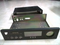
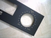
Yes. I think its a right suggestion. Actually, i already have a cabinet for my new amplifier project. It has a tone controls: Bass, treble and balance. So i am bound to use some preamplifier before my k50kit. I can't leave the tone controls dumb at the working amplifier. This will be very odd to have the dumb controls at the working amplifier cabinet. However, active preamplifiers mostly produce too much output to fed into the k50 kit.
I don't have any good passive design schematic suitable for k50 kit. I am littlebit confusing about what to use with k50. What is the perfect match with k50. My inputs will be mainly my computer soundcard, my lappy, two of my cd players, ipod and some of my boombox line outs.
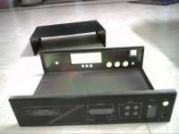
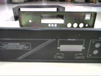
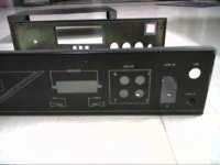
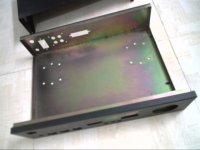
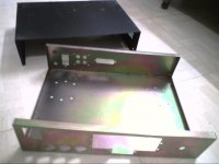
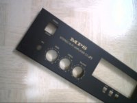
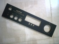
Please, have a look of my amplifier project cabinet pics attached.
Thanks.
No, they have no direct relation.
Thanks! I was too worried and confused about this because in most of the boomboxes and stereo systems, i have always and only seen the same or nearby values for input impedance and the NF capacitor. In some of the systems, volume control(50k) itself acts as the input impedance for power amplifier and the NF capacitor used is 47uf.
They are usually in the range of a few hundred Ohms.
Yes. 4.7K = 4700 ohms. Generally the line out impedance ranges between 1100 ohms to 5600 ohms, or may be somewhat different also. So, the input impedance of 22K is not sufficient for a line out boombox with 4700 ohms impedance.
If you have a preamp, put the volume control there, too and forget point 7.
Yes. I think its a right suggestion. Actually, i already have a cabinet for my new amplifier project. It has a tone controls: Bass, treble and balance. So i am bound to use some preamplifier before my k50kit. I can't leave the tone controls dumb at the working amplifier. This will be very odd to have the dumb controls at the working amplifier cabinet. However, active preamplifiers mostly produce too much output to fed into the k50 kit.
I don't have any good passive design schematic suitable for k50 kit. I am littlebit confusing about what to use with k50. What is the perfect match with k50. My inputs will be mainly my computer soundcard, my lappy, two of my cd players, ipod and some of my boombox line outs.
Please, have a look of my amplifier project cabinet pics attached.
Thanks.
Attachments
-
 2012-02-20-75303.jpg287.7 KB · Views: 102
 -
 2012-02-20-75285.jpg298.1 KB · Views: 97
 -
 2012-02-20-75268.jpg265.7 KB · Views: 80
 -
 2012-02-20-75199.jpg279 KB · Views: 77
 -
 2012-02-20-75141.jpg285.5 KB · Views: 97
 -
 2012-02-20-74908.jpg274.5 KB · Views: 1,096
 -
 2012-02-20-74732.jpg288.6 KB · Views: 1,124
 -
 2012-02-20-74687.jpg285.6 KB · Views: 1,190
 -
 2012-02-20-74546.jpg309.2 KB · Views: 1,281
 -
 2012-02-20-75432.jpg256.7 KB · Views: 123
Anyway, is there room in that box for a second power supply?
Yes! daniel there is lot of room in my box. You can see the pics now.
Any suggestions? for preamp? Active or Passive? for LM1875.
Any other better schematic?
Thanks.
If I were you, I'd create a new front panel for it. You can use a nice piece of thin decorative wood or you can use a nice bit of steel or aluminum textured any way you like and then sprayed with clear lacquer.
If you still happen to want a baxandall (bass-n-treble) then check Rod Elliot's site for some especially doable designs that can work well. But, don't forget to arrange a cancel switch for any sort of effects or tone controls. For an organized approach, consider preamplifier/effects/tone as a separate project even if it might happen to occupy the same enclosure and that way you can build modular, a nice doable step at a time.
If you still happen to want a baxandall (bass-n-treble) then check Rod Elliot's site for some especially doable designs that can work well. But, don't forget to arrange a cancel switch for any sort of effects or tone controls. For an organized approach, consider preamplifier/effects/tone as a separate project even if it might happen to occupy the same enclosure and that way you can build modular, a nice doable step at a time.
Thanks!
1.This requires skills and tools. I posses neither of them. I never worked with wood or steel or aluminium or a paint. But, i would like to learn if someone could take a pain to teach me all about this...........................
2.Please, answer my post 7. I need to discuss and clear the doubts about some points in your post 2.
Thanks.
If I were you, I'd create a new front panel for it. You can use a nice piece of thin decorative wood or you can use a nice bit of steel or aluminum textured any way you like and then sprayed with clear lacquer.
1.This requires skills and tools. I posses neither of them. I never worked with wood or steel or aluminium or a paint. But, i would like to learn if someone could take a pain to teach me all about this...........................
2.Please, answer my post 7. I need to discuss and clear the doubts about some points in your post 2.
Thanks.
The K50 resistor values of 180k/10k are simply too high and that is lossy/noisy enough to interfere with sound quality somewhat.
1M/18M is likewise inappropriate resistor values that will cause inferior sound quality. The inappropriate resistor selections are the cause of trouble, not related to a particular gain setting.
Post 7 contains two different questions at the same time, like apples and oranges in the same basket.
So, here is the second part. . .
LM1875 can use gain from 10 to 44 without any sound quality problems whatsoever.
So, how to you set your gain? Start out orthodox and see if your source can push the amplifier to BARELY begin clipping without also causing the source to strain. If a source cannot push the amplifier or if it strains to do so then turn up your power amp gain.
Step 1: Build amplifier.
Last edited:
hey im new to the forum but ive been reading some about the LM1875 now and i going to use it in my amp.
couz its for a stereo theres gona be 2 of them with exact the same schema
so ive been reading this post and i modified te K50 kit as you would recommend.
i hope its any good so i can build it.
already thanks for the help.")
couz its for a stereo theres gona be 2 of them with exact the same schema
so ive been reading this post and i modified te K50 kit as you would recommend.
i hope its any good so i can build it.
already thanks for the help.
An externally hosted image should be here but it was not working when we last tested it.
Just Bumped into this Thread.
Post14:
The four ground symbols on the left are all Signal Ground (SG). Connect them all together.
The six ground symbols to the right (excluding X4, Speaker Return) are all Power Ground (PG). Connect them all together.
Do not bring Speaker Return (SR) onto the PCB.
Take SG. & PG. & SR. to the Main Audio Ground.
Last edited:
I hope you don't mind using an old topic for a question about the LM1875?
I use a LM1875 poweramp module that has a 1M resistor from input to ground, just like in the datasheet. I understand why it is there, but I have a hard time figuring out how to match the inputimpedance of this module with my preamp outputimpedance.
From what I understand, the input impedance of the LM1875 is set by the 22K resistor right before the chip. Am I right by saying that the actual outputimpedance of my preamp is Zout ll 1M ? And does that mean that the Zout needs to be around 2k to get a good match (10x smaller than Zin of the poweramp)?
Thanks!
Hi Skullgoof,
Please, change the values of the component as suggested by daniel before bying any components. And do have some space for experimentation with different values in order to get the exact sound that meets your taste and preference, obviously inside the range values only. Thanks.
Please, change the values of the component as suggested by daniel before bying any components. And do have some space for experimentation with different values in order to get the exact sound that meets your taste and preference, obviously inside the range values only. Thanks.
There's no need to look at the 1M which is a noise filter that usually does nothing.I hope you don't mind using an old topic for a question about the LM1875?
I use a LM1875 poweramp module that has a 1M resistor from input to ground, just like in the datasheet. I understand why it is there, but I have a hard time figuring out how to match the inputimpedance of this module with my preamp outputimpedance.
From what I understand, the input impedance of the LM1875 is set by the 22K resistor right before the chip. Am I right by saying that the actual outputimpedance of my preamp is Zout ll 1M ? And does that mean that the Zout needs to be around 2k to get a good match (10x smaller than Zin of the poweramp)?
Thanks!
If you have a solid state preamp, all you have to look at are resistors that are in series with the preamp audio output. That will tell you more about output impedance of your preamp.
The power amp can easily compensate for a variety of input loads, since that "22K resistor right before the chip" can be replaced with a 5.6K to 56K variable resistor. You'd just solder a 5.6K resistor to the center pin of a 50K pot and use resistor and 1 of the outboard pins of the pot so that the range of travel is 5.6K+0 to 5.6K+50K for this variable dial. When you find the best sounding resistor value, simply replace the trimmer with an ordinary resistor of approximately that same value.
Line level preamps are probably not useful with LM1875 since it is 27 watts yet able for gain more than 45x, so even a little digiplayer or iphone can push that chip well into overdrive. I wonder what the preamp is for? Maybe a microphone, tape or turntable preamp?
Thanks Daniel,
It is a guitarpreamp I build myself, I use the LM1875 as a poweramp and all this goes into a guitarcombo with a nice speaker.
The guitarpreamp is a copy of a marshall solidstate preamp, which normally has a 1M mastervolume at the output (followed by a FET poweramp). But that doesn't match the input impedance of the LM1875 module, so I try to figure out what's the best value for the mastervolume.
Hi Rutger
referring to the circuit diagram in post 1, I would change R3 from 22K to 180K so that it matches R5. This will also be an easier load for your preamp to drive. Having done that, C1 can be reduced, say to 0.1uF plastic film. R1 and R2 can be left out, they don't do anything useful.
The mastervolume potentiometer should probably be a lower value, say 10K to 100K.
- Status
- This old topic is closed. If you want to reopen this topic, contact a moderator using the "Report Post" button.
- Home
- Amplifiers
- Chip Amps
- Understanding and redesigning the input stage of LM1875