Hey guys i made tda7294 and 2sc5200/2sa1943 with a toroid 30+30 5+5 amp, but not sounds good under 8 ohm load and distorts a lot on high volume, example 4 ohm 2/8 ohm woofers in parallel , i did exactly of the schematic, the heatsink which i m using it's good at high volume the ic and transistors are always cold.
what could be the problem?
what could be the problem?
Have a look at the output with a scope and then you will see what kind of distortions that you are having.
It will be either clipping (flat topping of the waveform's) or crossover distortion (notches at the center points of the waveform).
If your power supply can't supply enough current then these types of distortions can occurr when attempting high power levels.
jer")
It will be either clipping (flat topping of the waveform's) or crossover distortion (notches at the center points of the waveform).
If your power supply can't supply enough current then these types of distortions can occurr when attempting high power levels.
jer
thanks for reply geraldfryjr!
So i don't have a scope, but i will see what i can do this weekend!
I forgot to say which when the amp is running at 4 ohm load the sound distorts at low volume also, as you said start to clipping
In 8 ohm it's completely clean and no distortion at maximum or low volume
And one more thing, i don't found the resistors 0,15R, i just found 0,47R, i don't know if that change anything
Thanks for reply gootee
So,i don't understand what you said about the resistors,parallel is for have more watts or less resistance?
Both. Paralleling a number, n, resistors all of same value gives result of value/n. Power handling is also increased, since the current in each resistor is also divided by n, and power = i²R.
About the caps, i will buy more four, two each rails
You can calculate the minimum required capacitance, instead of guessing. The equation, and a spreadsheet for that, are in the post at:
http://www.diyaudio.com/forums/power-supplies/240955-resevoir-capacitors-chip-amps.html#post3599692
Hi guys !! I have a few questions about the amp design. I'm going to use the following: simetrical power supply 35-0-35 AC (about 45-0-45 DC after rectifier) TDA7293 + 2SC5200 + 2SA1943 and a 4 ohm speaker. First: how much power will I get with this configuration (+ losses). Second: how do I control the bias voltage ? Third: will the 15A limit of the transistor be an issue and if I use 2 pairs of 2SC5200/2SA1943 in paralel will it be less risky for me to burn the bipolars ? My goal is not to obtain more power with the second pair of 2sc5200/2sa1943, but to make it less risky for them to burn out. Thanks in advance !!
EDIT: Fourth: how much voltage can I pump into the 2sc5200/2sa1943. Can I go up to 90-0-90 v for the bipolars, and 45-0-45 volts for the TDA7293 ?? And do I need more pairs of 2sc5200/2sa1943 (like 6x2sc5200/6x2sa1943)to cope for the new voltage rating, power output, maximum amps output, so they won't burn out ??
EDIT: Fourth: how much voltage can I pump into the 2sc5200/2sa1943. Can I go up to 90-0-90 v for the bipolars, and 45-0-45 volts for the TDA7293 ?? And do I need more pairs of 2sc5200/2sa1943 (like 6x2sc5200/6x2sa1943)to cope for the new voltage rating, power output, maximum amps output, so they won't burn out ??
Last edited:
Well, 45 VDC minus the Vclip voltage across the amplifier itself will probably be around 42 VDC and if we assume the ripple voltage will be <= 2 V then we have 40 V max peak across 4 Ohms which would push 10 Amps max peak. But that's "peak" and power ratings are given using RMS. So dividing by sqrt(2) gives 28.28 V RMS sine wave voltage pushing 7.071 Amps RMS sine wave current through 4 Ohms. Rated max power is then either v²/R or i²R, which both equal 200 Watts RMS rated max output power.
But that depends entirely on the ripple voltage being less than or equal to 2 Volts. And the ripple voltage limit depends entirely on the value of the reservoir capacitance.
For the conditions assumed, you would need at least 44000 uF per rail, to get 200 W rated max power. With 20000 uF, you would get about 179 Watts rated max. And with 10000 uF you would get about 148 Watts rated max.
If the Vclip voltage is different than the assumed 3 Volts, those figures would change somewhat.
You can see how to calculate that, and download the spreadsheet for it, in the post at:
http://www.diyaudio.com/forums/power-supplies/240955-resevoir-capacitors-chip-amps.html#post3599692
Cheers,
Tom
Note that my capacitance figures above assume that you have 60 Hz AC mains, sicne you didn't yet specify your location.
For 50 Hz mains, you would need to add about 20% to those values.
And you should probably recalculate them using Vclip = 4 Volts, just to be a little more conservative.
For 50 Hz mains, you would need to add about 20% to those values.
And you should probably recalculate them using Vclip = 4 Volts, just to be a little more conservative.
Hi all.
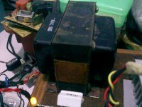
Today I made this amplifier with TDA 7293, 2SA1943 and 2SC5200. It was powered with toroid transformer 2x 30V/3.75A and 2x 10 000 uF capacitors (just for first test, so if something goes wrong and they blow up I lose less money. I plan to replace them with 15000 uF x4).
It didn't work. Output was giving DC signal from 2SC5200 with slight 50 Hz hum. I thought I solder something wrong, so I checked everything and solder again some suspicious spots. After that I turned it on again, but this time TDA blew off, probably because of too high current. I have absolutely no idea what I did wrong. It's probably some rookie mistake or something, but can't tell where it is.
Any help is appreciated.
this is new one:
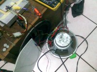
the second clone, 3886 with a fbstrg : 22k-1k-47uf, testing alone with a +-43VDC psu, no local pscaps, and with the speaker lose onthe floor, added a tweeter with a paper cap;It´s running warm and sounds good - not so loud but the speaker is very bad and i think its kind of hard or sticky or something but its very ineficient. i´m getting decent bass for the kind of situation...
after burn in i´m going to fit a pair of MJL3281A/1302A and test again.
the speaker is moving around, vibrating with the o freq content of the music!
added a 3.3uf film inputcap.
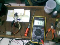
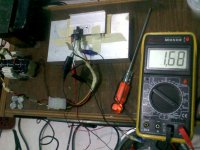
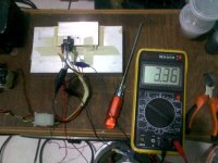
the meter is showing ac volts across the speaker terminals.
it has .5 mV dc voltage at the output, no signal.No noise, depends on the input cabling, just needs firm connection and noises go away.
the second clone, 3886 with a fbstrg : 22k-1k-47uf, testing alone with a +-43VDC psu, no local pscaps, and with the speaker lose onthe floor, added a tweeter with a paper cap;It´s running warm and sounds good - not so loud but the speaker is very bad and i think its kind of hard or sticky or something but its very ineficient. i´m getting decent bass for the kind of situation...
after burn in i´m going to fit a pair of MJL3281A/1302A and test again.
the speaker is moving around, vibrating with the o freq content of the music!
added a 3.3uf film inputcap.
the meter is showing ac volts across the speaker terminals.
it has .5 mV dc voltage at the output, no signal.No noise, depends on the input cabling, just needs firm connection and noises go away.
Attachments
Last edited:
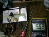
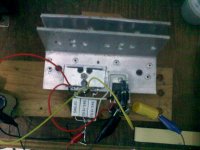
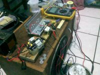
hi it´s alive!
Here´s it with the 2SC5200/2SA1943 pair. It was running very warm by itself, maybe hot; it might had to do with the thin heatsink, and it was lying on its back, the 46V rails etc. Now its warm to cold and sounds OK! bass is deep and clear punchy even tho i´ve the bare speaker lying on the floor. still need to test on 4 ohms. Haven´t tested fets, was about to get a MJL3281/1302A pair, but did not wait.The mids are really good with 3886, need to test with better speaker for lows; highs are nice with my old paper cone tweeter thru old paper cap, destiny speakers are two 8 ohm -4x6in driver- cabinets.So you just need to try...
Here´s it with the 2SC5200/2SA1943 pair. It was running very warm by itself, maybe hot; it might had to do with the thin heatsink, and it was lying on its back, the 46V rails etc. Now its warm to cold and sounds OK! bass is deep and clear punchy even tho i´ve the bare speaker lying on the floor. still need to test on 4 ohms. Haven´t tested fets, was about to get a MJL3281/1302A pair, but did not wait.The mids are really good with 3886, need to test with better speaker for lows; highs are nice with my old paper cone tweeter thru old paper cap, destiny speakers are two 8 ohm -4x6in driver- cabinets.So you just need to try...
Attachments
Last edited:
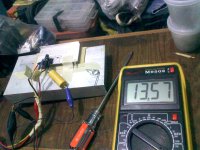
hello wiljj78: check this one is very good same circuits with some mods: 2x470uF very close to the chip, local decouple, 3.3uF input film cap and 47uF fbcap. Also higher V rails +- 43.6V noload sounds really good and runs cool! with just a chunk of aluminum from an angle piece, cut and riveted.
stewin have youtried fets? maybe Mr drFrost could tell or someone who has some experience?
stewin have youtried fets? maybe Mr drFrost could tell or someone who has some experience?
Last edited:
Martin,
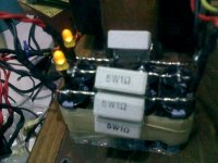
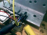
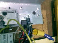
your clamp on the two output transistors has just one bolt between the devices.
This is very likely to give a poorer thermal transfer than using the normal one bolt through each transistor.
If you adopt clamping instead of through bolting, then you must use a mechanical system that ensures the whole transistor backplate has even contact pressure across it's whole surface. This is normally achieved by inserting at least one bolt on each side of every device and located fairly close to each device.
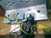
Hi there everybody, this amp is very good sounding and cool, still have to check at 4 ohms, full bast.
Mr. Andrew, used this way of clamping the transistors, copying from another amp, but as you pointed maybe i will change that to a larger piece of metal and use two screws, or three? Thanks for your attention!
Still waiting for those MJLs! maybe for the double pair of transistors amp, next amp.
Mr. Andrew, used this way of clamping the transistors, copying from another amp, but as you pointed maybe i will change that to a larger piece of metal and use two screws, or three? Thanks for your attention!
Still waiting for those MJLs! maybe for the double pair of transistors amp, next amp.
- Home
- Amplifiers
- Chip Amps
- TDA7294 + Power Transistors AMP (TDA7293 to come also)