Looks good Anir, I bet it was a fun project. I would like to see a schematic when you get the time.
Attached are the schematics
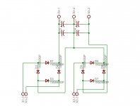
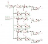
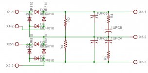
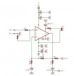
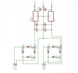
for LM3886 and LM1876 amplifier : I added DC blocking capacitor (1uf and 47k) and a high pass filter with 470pf and 680Ohm to amplifier boards externally by removing one of the resistor and soldering directly on backside of PCB. I also added 220pf capacitor between the input pins,
I don't have schematic of LM1876, but i used the same as given in datasheet.I directly created board for this amplifier as i was not able to find proper eagle library for lm1876, one which i used does not align with the pins of lm1876, I somehow managed to stretch the pins of IC and mounted it on the PCB.
I have not used any of the 3 pin connectors for connecting potentiometer shown in active filter schematic as it was resulting in lots of noise, I just shorted the pins and used final output pins of filter board to connect potentiometer.
Values of resistor and capacitors are calculated using esp-lr13.exe program available on this link (Linkwitz-Riley Electronic Crossover)
Crossover frequencies chosen are below
Sub : 112.5 Hz (lowpass)
Mid Woofer : 75~900 Hz (Bandpass)
Mid Range : 750 ~ 3500 Hz (Bandpass)
Tweeter : 3500 Hz (HighPass)
1n5408 board is used for power supply of midrange and tweeter (2 x LM1876)
2 x MUR860 board are used for Subwoofer and mid woofer amplifier (4 x LM3886)
1n4008 for active filter power supply.
Thanks! I was wondering if you used the Linkwitz-Riley.
Very nice project indeed. I hope you enjoy it.
Very nice project indeed. I hope you enjoy it.
really cool... must be enjoying listening them...
where u got the PCBs made?
also chk out my 5.1 home theater system 🙂
where u got the PCBs made?
also chk out my 5.1 home theater system 🙂
Hi Kuldeep,
I got the PCB made 3 years ago from AV process , pune
Av Process, Sadashiv Peth, Pune, India on Askme
I started this project 3-4 years ago, but left it in the middle because i was tired finding out the components in local market. Fortunately i got my enthusiasm back 2 months ago, did lots of travelling in pune local electronics market and lamington road (mumbai) and finally I finished this project 🙂
I almost explored most of online resources(pics and schematics) for DIY chipamps, I have seen your project webpage earlier, it looks awesome!
Thanks,
Aniruddha
Hii Aniruddha.....nice to see people from pune active on DIYaudio.....
i am new on diyaudio.....
currently looking for a good amp for subwoofer.....to add to my existing stereo speakers....will take ur help......
i am new on diyaudio.....
currently looking for a good amp for subwoofer.....to add to my existing stereo speakers....will take ur help......
saw ur work on google+ ......awesome work man.......
Here is my existing stereo system.....to which i need to add the SUB.....
http://www.facebook.com/media/set/?set=a.1697852484611.2095179.1186835873&type=3
Here is my existing stereo system.....to which i need to add the SUB.....
http://www.facebook.com/media/set/?set=a.1697852484611.2095179.1186835873&type=3
- Status
- Not open for further replies.
- Home
- Amplifiers
- Chip Amps
- Pics of my new 4 way active filter and amplifier using NE5532 LM3886 and LM1876