This thread is the result of an attempt to primarily gain knowledge on the topic of safely and effectively wiring multiple toroid transformers in a MyRef based “integrated “build. Secondarily, I was not able to find a site or comprehensive point of reference for the need and use of devices such as soft-starts, relays, thermistors and other current inrush limiting methods for the general chipamp builder.
Throughout my experience with LM3886 projects I have tried to stick to the “KISS” or “less is more” concept. Short leads and cables, efficient component placement and the elimination of loops and crossovers are readily achievable with mono-block and two channel amps. Integrating preamps, buffers, volume control devices, DACs and remote control access surely complicate matters. A few builders have even expressed a desire to build a complete receiver based around the MyRef amp.
So let’s give it a shot.
-------------------------
Some other posts related to integration can be found here:
http://www.diyaudio.com/forums/chip-amps/54571-my-audiophile-lm3886-approach-343.html#post2839322
http://www.diyaudio.com/forums/chip-amps/201336-softstart-new-guy-question.html
http://www.diyaudio.com/forums/chip-amps/192604-myrefc-volume-control-thread.html#post2639017
http://www.diyaudio.com/forums/construction-tips/202968-my_receiver.html
In summation - All comments, techniques and photos dealing with multiple transformers, inrush solutions and general integration are welcomed and encouraged!
I’ll begin with some information and communication related to one of my projects.
It started with two V1.3 MyRef amps with discrete transformer and a Lighter Note/Lightspeed – with the third transformer. That system provided adequate SPL with my great sounding but low efficiency speakers. For my personal tastes, there was an apparent need for just a bit more gain when playing some CDs. Subsequent mods to the amps clearly bumped up the output but the volume pot was still in the 90% + area. Again, I’m talking about playing “loud” and not casual listening, and not with all program material. Thus, the desire to add a device that gives the system some “breathing room” and not have everything at or near max.
Here’s a related quote from the Pass DIY site:
.........“I suppose if I had to floor the accelerator to drive 55 mph, maybe I’d think the life was being sucked out of my driving. Then again, maybe I like 55.Nice and safe, good gas mileage…”
I settled on adding a Class A pre fed by a Lighter Note as a good place to start. That’s a fourth transformer. Knowing Andrew T. had the experience and technical expertise to point me in the right direction, the following conversation ensued:
NOTE: from Andrew’s response to starting this thread – “I don't mind you including/stating that I consider safety above all else. That is because it does influence some, or indeed many, of my audio decisions.”
bcmbob -
Hi Andrew,I need some of your transformer knowledge. A build I’m doing has four toroids.
2 X 24V for discrete power for two MyRefs.
1 X 18V for JC-2 Preamp
1 X 12V for Lighter Note.
I have come up with a scheme using combined/soldered leads ending at a two point euro style block. I’m not sure that is the best way to do it as opposed to a ganging strip.
The opening of the can in thepictures will face down against the floor of the chassis and there will not be a shock hazard if I use a gang strip.
This is the first time I have used dual secondary’s for the MyRef (as opposed to doing 4 to 3 --- Hot-Gnd/Gnd-Hot) and am assuming as long as I stay consistent (Blue always hot – Green always gnd) on all the boards it will be correct.
The reason for this approach (the big shield) is my plan to have an ITX based computer+ DAC in a twin chassis that sits above the MyRef build.
So would you give a recommendation / critique on the mains in method.
Thanks, Bob M.
http://www.diyaudio.com/forums/gallery/showphoto.php/photo/7258
http://www.diyaudio.com/forums/gallery/showphoto.php/photo/7253
http://www.diyaudio.com/forums/gallery/showphoto.php/photo/7254
-------------------
Andrew T. –
“The first concern is lack of fuses to the 4 mains transformers.Will any of these transformers start direct on line with a close rated fuse?You may need soft start on some or all. One soft -start with 4 relays across 4 limiting resistors after the four fuses.
I don't understand the remainder of your enquiry.
Regards
Andrew T.
---------------------
bcmbob –
Thanks for your response,
The attached picture is my standard configuration for mains in. The twisted R/B wires coming off to the left would terminate at the euro style block in the second picture. I used that configuration successfully with two of the ApexJr -2 x24-0 toroid transformers for the MyRefs and single -2 x 15V for the Lighter Note (pic 3).
But you are telling me a single fuse is not sufficient for all four transformers – right? There was no soft start used. I did get a short diminishing (one second) hum at power-up, but Uriah told me to expect that till I got the LN in a metal case and grounded.
Is there such a thing as a quad or four-way soft start or will it require individual units. With two MyRefs, one Pre and the Lighter Note, is there any timing/sequence element that needs to be considered?
The part you didn.t understand is simply the fact that I have always combined the four wires from dual secondaries to a “power-common-power” state that I think of as something like +/-/+ (for the three power tabs on the Twisted Pear V1.2 board).
Fortunately I’m using all Antek toroids that have consistent colors for the secondary wires (Blu-Grn-Blu-Grn). I’m assuming that if I think of one color as hot on every board involved, I’ll not get something backwards – such as when using the second ground on Siva’s V1.3 PBCs. I may be naive in unnecessarily considering all this with AC, but I’d rather ask a silly question as opposed to smelling “green Smoke”
http://www.diyaudio.com/forums/gallery/showphoto.php/photo/7255
Thanks, Bob
----------------------------
Andrew T –
“You may need soft start on some or all. One soft -start with 4 relays across 4 limiting resistors after the four fuses.
A soft start is simply a timer, a relay and a resistor.
Imagine I am building your arrangement but on a 110Vac supply.
I choose two 200VA for the chipamps and 100VA for the pre-amp and 50VA for the Lighter note. That's a total of 550VA run off 110Vac or 5Aac for a close rated fuse.
To start all 4 transformers simultaneously without any nuisance blowing I may have to fit a T10A or even larger fuse.
A T10A may pass 20Aac for many minutes and possibly upto half an hour before it ruptures.
Let's suppose only one piece of your kit has gone faulty and overloaded one transformer. That transformer is going to get mighty hot, mighty quickly dissipating 2kW and I am outside doing a bit of gardening, while the curtains or the carpet catches fire.
Does close rating and individual fusing start to make sense?
You can still use a master fuse at the mains cable inlet, I would recommend that anyway.
Now back to the relays.
four 5V relays in series would require an LM317 set to 20Vdc.
four 12V relays could be set to run off 12Vdc or 24Vdc.
four 24V relays could be set to run off 24Vdc.
Your system will run from 4 transformers. Could one of those transformers supply 20Vac (just one winding)? That would give ~25Vdc to 30Vdc depending on operating conditions. This could be the supply for the relays.
I would go a little higher and use 25Vac and regulate that down to 30Vdc and run the 24V relays off the 30Vdc with a dropper resistor in series with each relay coil. Saves the coils getting hot and triggers the relays faster to close and releases the relays faster to open. The resistor would have a value ~ = to the relay coil resistance. The relays will then run at 15Vdc but trigger from 30Vdc. A 100uF cap stores enough energy to trigger the 4 relays before the dropper resistor takes effect.
If you do use one of the four transformers to power the soft start then that one transformer should not be fitted with a soft start. Choose a low VA transformer for this and that allows a low value Tfuse to be used @ ~3times the close rated value. eg 50VA needs ~ T500mA for close rating with a soft start. But without soft start it may run (and start) from a T1.2A or T1.6A fuse.”
- - - - - - - - - - - - -
bcmbob –
Fantastic Andrew, very clear and informative. As usual, you’ve prodded me off to study hall to enter a new dimension of this hobby.
Thanks Much - Bob
It started with two V1.3 MyRef amps with discrete transformer and a Lighter Note/Lightspeed – with the third transformer. That system provided adequate SPL with my great sounding but low efficiency speakers. For my personal tastes, there was an apparent need for just a bit more gain when playing some CDs. Subsequent mods to the amps clearly bumped up the output but the volume pot was still in the 90% + area. Again, I’m talking about playing “loud” and not casual listening, and not with all program material. Thus, the desire to add a device that gives the system some “breathing room” and not have everything at or near max.
Here’s a related quote from the Pass DIY site:
.........“I suppose if I had to floor the accelerator to drive 55 mph, maybe I’d think the life was being sucked out of my driving. Then again, maybe I like 55.Nice and safe, good gas mileage…”
I settled on adding a Class A pre fed by a Lighter Note as a good place to start. That’s a fourth transformer. Knowing Andrew T. had the experience and technical expertise to point me in the right direction, the following conversation ensued:
NOTE: from Andrew’s response to starting this thread – “I don't mind you including/stating that I consider safety above all else. That is because it does influence some, or indeed many, of my audio decisions.”
bcmbob -
Hi Andrew,I need some of your transformer knowledge. A build I’m doing has four toroids.
2 X 24V for discrete power for two MyRefs.
1 X 18V for JC-2 Preamp
1 X 12V for Lighter Note.
I have come up with a scheme using combined/soldered leads ending at a two point euro style block. I’m not sure that is the best way to do it as opposed to a ganging strip.
The opening of the can in thepictures will face down against the floor of the chassis and there will not be a shock hazard if I use a gang strip.
This is the first time I have used dual secondary’s for the MyRef (as opposed to doing 4 to 3 --- Hot-Gnd/Gnd-Hot) and am assuming as long as I stay consistent (Blue always hot – Green always gnd) on all the boards it will be correct.
The reason for this approach (the big shield) is my plan to have an ITX based computer+ DAC in a twin chassis that sits above the MyRef build.
So would you give a recommendation / critique on the mains in method.
Thanks, Bob M.
http://www.diyaudio.com/forums/gallery/showphoto.php/photo/7258
An externally hosted image should be here but it was not working when we last tested it.
http://www.diyaudio.com/forums/gallery/showphoto.php/photo/7253
An externally hosted image should be here but it was not working when we last tested it.
http://www.diyaudio.com/forums/gallery/showphoto.php/photo/7254
An externally hosted image should be here but it was not working when we last tested it.
-------------------
Andrew T. –
“The first concern is lack of fuses to the 4 mains transformers.Will any of these transformers start direct on line with a close rated fuse?You may need soft start on some or all. One soft -start with 4 relays across 4 limiting resistors after the four fuses.
I don't understand the remainder of your enquiry.
Regards
Andrew T.
---------------------
bcmbob –
Thanks for your response,
The attached picture is my standard configuration for mains in. The twisted R/B wires coming off to the left would terminate at the euro style block in the second picture. I used that configuration successfully with two of the ApexJr -2 x24-0 toroid transformers for the MyRefs and single -2 x 15V for the Lighter Note (pic 3).
But you are telling me a single fuse is not sufficient for all four transformers – right? There was no soft start used. I did get a short diminishing (one second) hum at power-up, but Uriah told me to expect that till I got the LN in a metal case and grounded.
Is there such a thing as a quad or four-way soft start or will it require individual units. With two MyRefs, one Pre and the Lighter Note, is there any timing/sequence element that needs to be considered?
The part you didn.t understand is simply the fact that I have always combined the four wires from dual secondaries to a “power-common-power” state that I think of as something like +/-/+ (for the three power tabs on the Twisted Pear V1.2 board).
Fortunately I’m using all Antek toroids that have consistent colors for the secondary wires (Blu-Grn-Blu-Grn). I’m assuming that if I think of one color as hot on every board involved, I’ll not get something backwards – such as when using the second ground on Siva’s V1.3 PBCs. I may be naive in unnecessarily considering all this with AC, but I’d rather ask a silly question as opposed to smelling “green Smoke”
http://www.diyaudio.com/forums/gallery/showphoto.php/photo/7255
An externally hosted image should be here but it was not working when we last tested it.
An externally hosted image should be here but it was not working when we last tested it.
Thanks, Bob
----------------------------
Andrew T –
“You may need soft start on some or all. One soft -start with 4 relays across 4 limiting resistors after the four fuses.
A soft start is simply a timer, a relay and a resistor.
Imagine I am building your arrangement but on a 110Vac supply.
I choose two 200VA for the chipamps and 100VA for the pre-amp and 50VA for the Lighter note. That's a total of 550VA run off 110Vac or 5Aac for a close rated fuse.
To start all 4 transformers simultaneously without any nuisance blowing I may have to fit a T10A or even larger fuse.
A T10A may pass 20Aac for many minutes and possibly upto half an hour before it ruptures.
Let's suppose only one piece of your kit has gone faulty and overloaded one transformer. That transformer is going to get mighty hot, mighty quickly dissipating 2kW and I am outside doing a bit of gardening, while the curtains or the carpet catches fire.
Does close rating and individual fusing start to make sense?
You can still use a master fuse at the mains cable inlet, I would recommend that anyway.
Now back to the relays.
four 5V relays in series would require an LM317 set to 20Vdc.
four 12V relays could be set to run off 12Vdc or 24Vdc.
four 24V relays could be set to run off 24Vdc.
Your system will run from 4 transformers. Could one of those transformers supply 20Vac (just one winding)? That would give ~25Vdc to 30Vdc depending on operating conditions. This could be the supply for the relays.
I would go a little higher and use 25Vac and regulate that down to 30Vdc and run the 24V relays off the 30Vdc with a dropper resistor in series with each relay coil. Saves the coils getting hot and triggers the relays faster to close and releases the relays faster to open. The resistor would have a value ~ = to the relay coil resistance. The relays will then run at 15Vdc but trigger from 30Vdc. A 100uF cap stores enough energy to trigger the 4 relays before the dropper resistor takes effect.
If you do use one of the four transformers to power the soft start then that one transformer should not be fitted with a soft start. Choose a low VA transformer for this and that allows a low value Tfuse to be used @ ~3times the close rated value. eg 50VA needs ~ T500mA for close rating with a soft start. But without soft start it may run (and start) from a T1.2A or T1.6A fuse.”
- - - - - - - - - - - - -
bcmbob –
Fantastic Andrew, very clear and informative. As usual, you’ve prodded me off to study hall to enter a new dimension of this hobby.
Thanks Much - Bob
Last edited:
Subscribed.
I am also doing a GC build at the moment.
I am trying to decide to go integrated or not. Integrated was the plan. I was ready to start cutting my 7mm aluminum when my table saw lost a bearing. I have never cut anything but wood on it, guess it freaked out when it saw the big chunks of aluminum coming.
Now I am able to cut it with a skill saw and straight edge, but it's so-so, needing to be cleaned up by hand. Not the best approach for accurate parts.
So I'm back to square one with a chassis. I could order one, but I usually like to make them. See what happens.
Anyways I'll be following along.
Hi GloBug,
With a large number of components I also considered buying a shallow 2U rack mount PC case. Since I have a good stock of flat and angle 1/4" aluminum, I'm designing my own with an eye toward the 17" W desktop standard.
Please be extra cautious cutting aluminum on your table saw if you haven't done it before. A "full-face" shield is highly recommended, no gloves to get caught and test your tolerances on wood first (no matter how many times I cut it - it's still to short ).
).
With metal it is also extremely important to push the workpiece fully past the blade to avoid the whole thing flying back at you. The investment in a high quality - high tooth count carbide tipped blade is also well worth the cost.
With a large number of components I also considered buying a shallow 2U rack mount PC case. Since I have a good stock of flat and angle 1/4" aluminum, I'm designing my own with an eye toward the 17" W desktop standard.
Please be extra cautious cutting aluminum on your table saw if you haven't done it before. A "full-face" shield is highly recommended, no gloves to get caught and test your tolerances on wood first (no matter how many times I cut it - it's still to short
With metal it is also extremely important to push the workpiece fully past the blade to avoid the whole thing flying back at you. The investment in a high quality - high tooth count carbide tipped blade is also well worth the cost.
Last edited:
I ordered one of these today. I plan to use it with the two biggest transformers to begin with. Still need to dial in relay requirements.
http://www.connexelectronic.com/documents/Power_SoftStart.pdf
http://www.connexelectronic.com/documents/Power_SoftStart.pdf
In my searches I found two 4-way terminal/fuse devices. Unfortunately one was designed for the flat automobile type fuse and the other (tube type) costs around $170. Four simple fuse holders like those sold at RS (~ $2 ea.) mounted side by side take only 1.5" x 1.5" and should be enough.
I suspect individual holders might be needed for optimum component placement.
I suspect individual holders might be needed for optimum component placement.
Yes,Do they make terminal blocks with fuse holders built in to them ?
but I don't remember which UK parts supplied sold them to me.
Oops ! Didn't look hard enough.
Amazon.com: Seachoice Fuse/Terminal Blocks 13431 4 Gang: Home Improvement
Fuse Blocks - Hot Feed
From boating world - manufactured up to 10 positions. Looks like a good choice if AC wring permits. In my case I'm retrofitting in a 80% complete chassis. Found them available at eBay now that I know who makes them.
Last edited:
Been snooping around for more pieces and parts. I actually bought the first item several months ago. Has surprisingly good sound. Could be switched/modded for USB/SD/FM before built-in amp in receiver build.
MP3 hardware decoder+Remote control unite | eBay
Other items for general consideration.
TDA7000 FM RADIO TUNER DIY KIT | eBay
4-Channel 12V Relay Module Board fr PIC ARM AVR DSP NEW | eBay
12V RF Wireless 4 Ch Remote Control Switch Controller | eBay
120W DC-DC Adjustable power supply 10-32V Boost 35-60V | eBay
Last edited:
The USS Battleship MyRef in drydock.
This is a very long post that might better belong in the photo gallery, but is placed here due to the specific “integrated” nature of the project. You know – kind of like the Big Bang Theory. Good things follow.
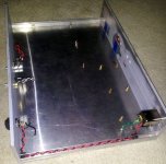
Chassis fabricated from 3”X3” X1/4 aluminum angle, ½”X3/8” “C” channel and thin aluminum floor.
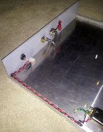
Open channel provides convenient path for mains in wires. Rubber grommets used for extra protection.
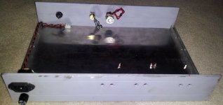
Back plate drilled for RCA in, out posts, AC inlet and fuse holder. Front panel with on/off switch and Lightspeed contro
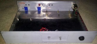
Reverse view
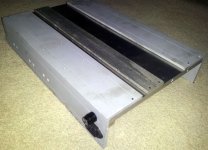
Under side construction. Plates drilled and tapped for 6-32 screws.
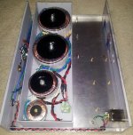
This is the transformer can upside down to show location relative to components. Shows there is not a lot of room for suggested soft-start, relays and fuses. Bottom to top – Lighter Note, JC-2 and MyRef x 2.
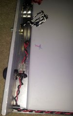
Can installed to allow space for LN controls. Terminal block allows removal of transformer can.
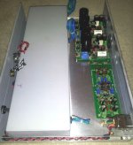
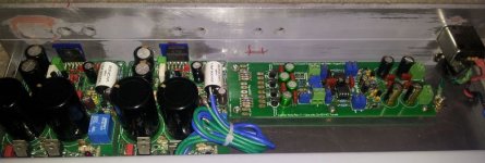
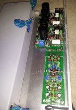
2 X MyRef V1.3 and Lighter Note mounted.
This is a very long post that might better belong in the photo gallery, but is placed here due to the specific “integrated” nature of the project. You know – kind of like the Big Bang Theory. Good things follow.

Chassis fabricated from 3”X3” X1/4 aluminum angle, ½”X3/8” “C” channel and thin aluminum floor.

Open channel provides convenient path for mains in wires. Rubber grommets used for extra protection.

Back plate drilled for RCA in, out posts, AC inlet and fuse holder. Front panel with on/off switch and Lightspeed contro

Reverse view

Under side construction. Plates drilled and tapped for 6-32 screws.

This is the transformer can upside down to show location relative to components. Shows there is not a lot of room for suggested soft-start, relays and fuses. Bottom to top – Lighter Note, JC-2 and MyRef x 2.

Can installed to allow space for LN controls. Terminal block allows removal of transformer can.


2 X MyRef V1.3 and Lighter Note mounted.
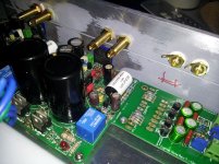
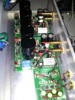
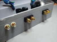
Vampire posts (long version as they were originally intended for DIY speakers) and Parts Express RCAs – all gold plated
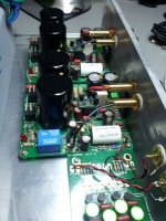
Temporary wires to show short lead lengths. I have two sizes of Neotech solid core wire for final assembly.
Plan II – add the JC-2 preamp to obtain additional gain. I had it 90% completed and messed up.
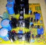
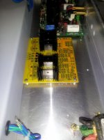
New board for second attempt. Heat sinks in place for height calculations
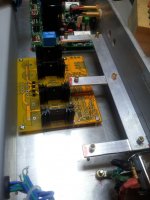
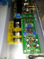
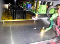
Bracket fabricated to allow proper air flow for JC-2 heat sinks.
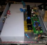
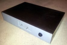
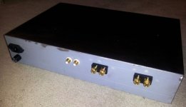
So there it is. I call it a battle ship because at this point, it weighs in at just over 25 pounds. If more room is needed for all of Andrew’s safety devices, front to back distance can easily be increased by the use of longer L/R “C” channels and chassis floor.
I’ve also considered replacing the Lighter Note with the Lightspeed to gain some room but want to check with Uriah first.
I should add the reason for the transformer can is my intention to build a twin chassis containing an ITX motherboard and DIY DAC to feed this integrated box with uncompressed audio files. Computers are infamously noisy – thus as much shielding as is practical.
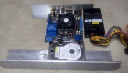
All questions, comments and suggestions are welcomed.
Shoot. Lost my post. Anyway,
Want more room? Turn it on its side. Use angle iron or some other 90 degree bracket. If its not tall enough then turn the 90 degree closer to 60degree.
LN can adjust Rtot giving best sound in that system. LS can not. LS with its board plus its power supply board is about half the size of a LN board so I can see the appeal but you can squeeze a lot of room by turning the LN on its side.
Uriah
Shhhaaaaa-wwweeeeeetttt! 
Thanks for all the pics - it gives me some really good ideas. I just finished two MyRef boards (with two more potentially waiting in the wings) and I am contemplating where I want to go with this and how I want to package it up - current thinking is active three-way crossover, possibly DSP. Not sure if I want to integrate it into a single chassis or spread it out. There are definitely some advantages to the one-stop-shopping method (as you have shown).
-bill
Yes, I was paid as a machinist for several years though my boss often expressed doubts that the title fit. 
Nowadays I don't often have full access to a complete shop but find it seldom necessary as long as I stick to aluminum and high grade carbide tipped tools. I usually find careful and accurate lay-out as important, if not more than the equipment used to make the cuts. Other than the inset in the front panel, the chassis is being built with a drill press, table saw, small band saw, power sanders and of course - the indispensable "Dremel Tool".
I keep telling myself - Rodin and da Vinci never had an eight axis CNC.


- Status
- This old topic is closed. If you want to reopen this topic, contact a moderator using the "Report Post" button.
- Home
- Amplifiers
- Chip Amps
- MyRef Integrated Solutions