I have a few Klipsch subwoofer plate amps collecting dust. 2 of them I plan to rebuild into full range amps. The other 3 I can't do much with as they have seperate power supplies/chip amps. The chip amps use alot of smd and small components and that's a mess I would rather not get into.
However these amps have smps power supplies that I would like to make use of. The amps are rated for 150W continuous and 350W peak. The power supplies have a regulated +-15V 1A and a DC output. I am not home to measure the output but as a guess its 24-60V.
Looking at datasheets most chip amps call for a +- supply. Is it acceptable to reference the -V to ground or do they require a bi-polar supply? I would like to make some small 120-150W amps to make use of these nice supplies. NXP has some nice higher power chip amps with relatively low THD that I am looking at in hopes I can use them. IF these supplies are not acceptable for a chip amp can someone recomend a topology that would beneit from these supplies?
Sure just look at page 6 but it sure gets more complicated to use a single supply.
http://www.national.com/ds/LM/LM3886.pdf
http://www.national.com/ds/LM/LM3886.pdf
More information is needed.The power supplies have a regulated +-15V 1A and a DC output. I am not home to measure the output but as a guess its 24-60V.
How many power supplies of what voltage and current capacity are available?
Imformation required
1 The actual votage and current rating of the psu.
2 The impedance of the speaker you intend to drive.
I suspect the amplifiers these PSU where powering are class d. If that is the case i suggest you go for a class d chip. this will also mean a small heatsink wich will enable you to build a small amplifier.
Regards Ian
I will measure the output voltage when I get home...Assuming 150WRMS I will be able to make a good guess output current.
I really like the NXP TDA8950 but I can't find information on a single supply.
The ST 7575B is my second choice.
More to come after I find the output voltage.
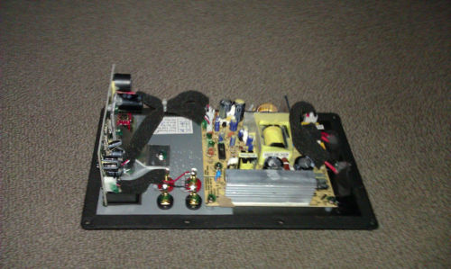
Here is a picture of the amp and power supply.
I really like the NXP TDA8950 but I can't find information on a single supply.
The ST 7575B is my second choice.
More to come after I find the output voltage.
Here is a picture of the amp and power supply.
Attachments
Last edited:
I measured the voltages. The main output is 48VDC with a +-9V secondary supply. The current is im guessing around 4-8A(150-350W). Expected speaker Z 4-8ohms. I am not sure what mode the SMPS runs in there is no feedback that I can easily see. The output is 5 wires. +42V GND -9V GND +9V. It may have some sort of current sensing, I'd have to look up the data sheets on the controller IC's.
The chip amplifier part of the amp is very "HIGH TECH" it uses this IC for who knows what. Seems a little over-complicated for a sub amp but I must say the thing does sound pretty crisp.
http://www.st.com/internet/com/TECHNICAL_RESOURCES/TECHNICAL_LITERATURE/DATASHEET/CD00169555.pdf
Its a shame that modifying the crossover on the amp is so complicated. It will be much simpler and way more fun to build a custom chip amp and just steal the SMPS.
Last edited:
The LM1875 chip will run on that 48v or 42v single rail just fine. This can get you about 24 watts of hi-fi. Remember that a speaker that just 3db more efficient makes up the difference between a 25 watt amp and a 50 watt amp.
If you'd like more power, select a stereo chip, such as one of ST's and bridge it. There's quite a few that call for 48v or +-24 and most of them have bridge options demonstrated in the datasheet. This can get you about 40 watts.
If I remember correctly, there is a Tripath kit that was specified for 48vdc, and it is possibly a bridged kit. This can also get you about 40 watts.
Are they not functional the way they are?I have a few Klipsch subwoofer plate amps collecting dust. 2 of them I plan to rebuild into full range amps.
42 V marked and 48 V measured? That is quite a big regulation for an SMPS. For your plan of 150 W, you will need 4 Ohm speakers and to use chip amps in (paralleled) BTL mode on single supply. That is about as complicated as it can get with chip amps.I measured the voltages. The main output is 48VDC with a +-9V secondary supply. [...]The output is 5 wires. +42V GND -9V GND +9V.
Or sou could try to make a split supply from two of those SMPS, and then choose a chip amp that can work from ±48 V rails, like the TDA7293.
That is the crossover. You won't need it for full-range amps.The chip amplifier part of the amp is very "HIGH TECH" it uses this IC for who knows what.
Are they not functional the way they are?
42 V marked and 48 V measured? That is quite a big regulation for an SMPS. For your plan of 150 W, you will need 4 Ohm speakers and to use chip amps in (paralleled) BTL mode on single supply. That is about as complicated as it can get with chip amps.
Or sou could try to make a split supply from two of those SMPS, and then choose a chip amp that can work from ±48 V rails, like the TDA7293.
That is the crossover. You won't need it for full-range amps.
The 2 Sub-12 plate amps I have are in pretty bad shape and not fixable the way they are. I am in the process of making a schematic and PCB. They run in class G with a linear full bridge amp.
48V marked and 42.5V measured loaded and unloaded. The SMPS boards are rather nice compact and covered in component glue. I would prefer to not modify them at the expense of having a more complicated chip amp. More challenge=more fun.
The SW-350 amps with these smps's are full digital chip amps. They use an a/d converter digital filtering and amplification. Down the road that might be a fun project to venture into but as my first real amp build I will stick with analog for now.
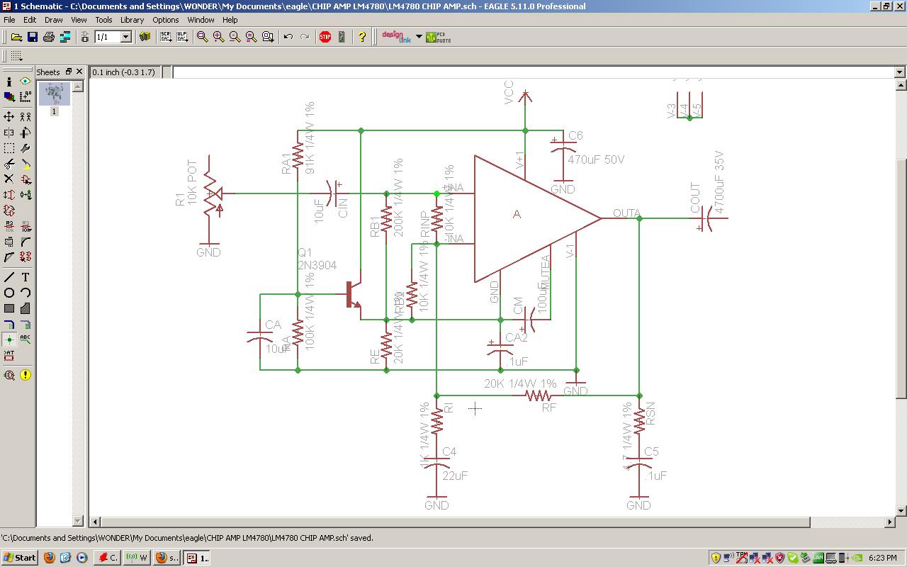
The chip I have selected to use is the LM 4780 basically the 2 channel version of the LM 3886.....Let the fun begin!
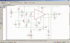
WOW!! You weren't joking about single supply being a pain. Bridged is out of the question for right now. I made my first schematic of this setup following the data sheet. Have a look and let me know if any of my values are no good. The data sheets states to use poly film caps in the signal path for better response.
Attachments
Since you adapted all values from the datasheet, you can assume that it will work OK like that.
And yes, you should use film caps in the signal path, where possible and affordable. For Cout that is clearly out of the question, although a small film cap in parallel to it will be an improvement. That leaves Cin and C4. Cin's 10 µF make it already quite expensive, and C4 is usually an electrolytic due to its size anyhow. In both cases you could achieve the values by paralleling cheap big electrolytics with small and affordable film caps.
And yes, you should use film caps in the signal path, where possible and affordable. For Cout that is clearly out of the question, although a small film cap in parallel to it will be an improvement. That leaves Cin and C4. Cin's 10 µF make it already quite expensive, and C4 is usually an electrolytic due to its size anyhow. In both cases you could achieve the values by paralleling cheap big electrolytics with small and affordable film caps.
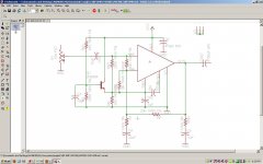
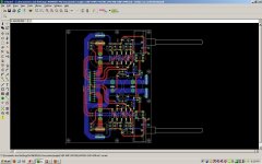
I updated the schematic and cleaned up the names and some other small stuff. I also completed v1 of the pcb. I added a .1uf film cap in parallel to Cin Cout and Ci. Higher values are much larger in size. If this is not sufficient changes can be made. For the electrolytics, mainly Cin and Cout are these meant to be polarized as seen in the data sheet or bi-polar?
I am sure the component placement could be stuffed in a little tighter but as it is this is a relatively compact design and I really like the symmetry of the board.
Once the design is ready I will edit the silkscreen on the pcb and make it pretty.


I am sure the component placement could be stuffed in a little tighter but as it is this is a relatively compact design and I really like the symmetry of the board.
Once the design is ready I will edit the silkscreen on the pcb and make it pretty.
Attachments
Last edited:
In a single supply amp the output is at half the rail voltage, e.g. for 42 V rails at 21 V. The size of the cap is due to its filter function. It forms a high-pass filter with the load, according to f = 1 / (2*PI*C*R), where R is the speaker impedance. A smaller capacitor could audibly cut the bass, depending on the speaker.Why such a large cap on the output. Does running a single supply add that much DC into the signal?
It is advisable to route power supply and output traces as far away as possible from the input to avoid crosstalk and (worst case) oscillation. Where you cannot avoid that they cross, they should do so at right angles. Take a look at the reference design in the datasheet to see how it is done.I also completed v1 of the pcb.
Watch that the big electrolytics are placed in a way that still allows you to reach the LM4780 with a screwdriver. Otherwise it will be difficult to fix it to the heatsink.
It is OK to connect the two mute pins in parallel and only use one capacitor and resistor for both channels. By the way the mute resistor seems to be missing in your design.
You should also add a 100nF ceramic cap next to the power supply pin and another 10 µF electrolytic no too far away from that. See chapter Supply Bypassing for that.
The Pareto principle works here. You can achieve 80 % of the result with 20 % of the investment. The next 20 % of investment bring you to 96 % of the result, the next 20 % investment to 99 %, and so on. The more money and PCB space you invest in those caps the smaller is the gain, but gain there is. I would qualify the electrolytics as the first 20 % of investement, parallel film caps as the next 20 %, have film caps of 1 % or more of the electrolytics value are another 20 %, replacing the electrolytics entirely with film caps another 20 %.I added a .1uf film cap in parallel to Cin Cout and Ci. Higher values are much larger in size.
Polarized.For the electrolytics, mainly Cin and Cout are these meant to be polarized as seen in the data sheet or bi-polar?
Last edited:
I updated the schematic and pcb adding in the capacitors for te Supply Bypassing. I dont plant to use any mute switch so the resistor and switch was left out of the design. I am going to build this board as a prototype and testing platform while I rework the PCB. Are there any final changes that I should make?
")
Unfortunately the majority of the output from a spike system chip severely under-run on voltage, is exacerbated hard clipping, that is not especially practical.
Instead of so much noise, why not use a simple chip that you can bridge? Perhaps 2 of these: http://www.st.com/internet/com/TECHNICAL_RESOURCES/TECHNICAL_LITERATURE/DATASHEET/CD00236549.pdf
The little brother of that chip has the single rail bridge application in its datasheet. See figure 18. http://www.st.com/internet/com/TECHNICAL_RESOURCES/TECHNICAL_LITERATURE/DATASHEET/CD00000145.pdf
Unfortunately the majority of the output from a spike system chip severely under-run on voltage, is exacerbated hard clipping, that is not especially practical.
Instead of so much noise, why not use a simple chip that you can bridge? Perhaps 2 of these: http://www.st.com/internet/com/TECHNICAL_RESOURCES/TECHNICAL_LITERATURE/DATASHEET/CD00236549.pdf
The little brother of that chip has the single rail bridge application in its datasheet. See figure 18. http://www.st.com/internet/com/TECHNICAL_RESOURCES/TECHNICAL_LITERATURE/DATASHEET/CD00000145.pdf
I see the point that you are making in that running at 1/2 the supply voltage will be running the chip close to the lowest supply voltage. I do not have the knowledge currently to design a circuit that will run on a single supply and also BTL. I would however like to gain more information on this. The LM4780 was a good starting point and I will still build the amp for a proof of concept/test platform. I would like to explore other chips and circuits that can be used with a single supply that will give good results as well. This project has pleanty of room to evolve and will be a good foundation for a learning platform on chip amps for me. The bridge application for the "little cousin" is for a split supply.
Could it be as simple as setting up the single supply in the same configuration as the split supply bridged?
Last edited:
- Status
- This old topic is closed. If you want to reopen this topic, contact a moderator using the "Report Post" button.
- Home
- Amplifiers
- Chip Amps
- DIY Chip Amp From Old Plate Amp Parts?