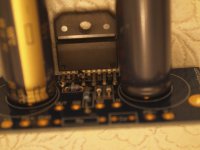
I am currently assembling a LM3875 amp using Peter Daniel (Audiosector) PCBs. First, the boards are gorgeous. Unfortunately, I am not as skilled as I would like at soldering. His instructions mention to make sure that pins 1 & 4 have solder on the top, as these are the power pins. All well and good on my first board. I only bridges pins 4 & 5. Pin 5 has no connection per the datasheet, so that isn't a problem. The first two images (both capacitors on board) are the good board.
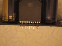
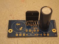
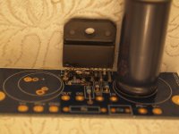
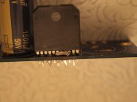
The second board, I managed to create a rather impressive solder bridge across pins 3-7. This is a problem. Pin 3 is output, pin 4 is negative rail, pins 5 and 6 are no connection, and pin 7 is non-inverting input. Obviously, I have not applied power to the board. I also removed the positive bulk capacitor to give myself a bit more room to work. The last three images (only one capacitor on board) are the bridged board.
Are there any suggestions for clearing these bridges? I have a desoldering bulb, desoldering braid, solder, and will have a Circuit Specialists station 1A. I was using an el-cheapo soldering iron, but managed to break a spot weld attaching the tip, so it is dead.
Attachments
You could try heating them and using the soldering iron to draw a little away.
Clean the iron and let the pins cool.
Try again, a couple of times and you should have broken the solder bridge.
One of the spring loaded solder suckers would also work well in this application.
Once the bulk of the solder is gone you can use the braid.
Fan the braid out a little.
Press the braid to the solder in question and the solder should wick into the braid.
If you have any liquid solder flux it can help to brush a little on before you place the braid onto the solder.
Like Einric said, use your desoldering bulb to remove the bulk of it, then clean up with braid.
Glad to hear you are getting a better iron, which will improve your ability to do fine work. I think those solder stations cone with a conical tip, which is OK, but a fine chisel tip is better. I don't think the instructions to make sure there is solder on the top of the board mean you need to apply solder to the top, but just to hold the heat on those pins a few seconds longer and flow in a little more solder, so you can see the solder from the top. I'm sure you are aware that what is pictured above is a bit of a mess, and is way too much solder.
Glad to hear you are getting a better iron, which will improve your ability to do fine work. I think those solder stations cone with a conical tip, which is OK, but a fine chisel tip is better. I don't think the instructions to make sure there is solder on the top of the board mean you need to apply solder to the top, but just to hold the heat on those pins a few seconds longer and flow in a little more solder, so you can see the solder from the top. I'm sure you are aware that what is pictured above is a bit of a mess, and is way too much solder.
Last edited:
My advice is to forget the braid for now. Using the far right pic for reference: Have the desoldering bulb ready ie squeezed in one hand, near the work. Apply the tip of the soldering iron to that blob on the top side of the board. Watch closely and you'll probably see the little "wave of heat" move across the surface of the blob as it melts; when it reaches the end of the blob, release the bulb and suck up as much solder as possible. This complete action should take maybe 2 or 3 seconds, and don't leave the iron applied to the leads. Repeat as necessary, but twice, maybe three times, should remove that topside blob.
Then do the same with the bottom side. Here I find it often works very well to place the nozzle of the solder sucker right over the end of the leads, with the iron applied to the remaining exposed part of the lead. Of course if it is a tight fit that won't work!
Once you've done that, put some flux on the joints and reflow the solder remaining on the leads, with the iron tip applied to both lead and pad (the pin 2 joint (2nd from right) in the second pic suggests the end of the lead was hotter than at the pad), applying more solder only if necessary. Hope this helps.
You can use a small file, with a right-angle edge, to remove the bulk of the solder. Thermally, this will be less intrusive.
I like this idea. I think this will be the first line of attack.
Like Einric said, use your desoldering bulb to remove the bulk of it, then clean up with braid.
Glad to hear you are getting a better iron, which will improve your ability to do fine work. I think those solder stations cone with a conical tip, which is OK, but a fine chisel tip is better. I don't think the instructions to make sure there is solder on the top of the board mean you need to apply solder to the top, but just to hold the heat on those pins a few seconds longer and flow in a little more solder, so you can see the solder from the top. I'm sure you are aware that what is pictured above is a bit of a mess, and is way too much solder.
I wish I had known what was meant regarding the solder. That would have avoided the whole fiasco. I thought he meant that solder had to be applied to the top of the board, and it spiraled from there. I will keep the tip suggestion in mind for the future.
Two further question regarding clearing the solder:
- Should I plan on heating from below the board and waiting for the heat to "climb" the pins?
- Should I plan on clamping/holding the chip onto a heatsink while applying heat?
I propose another method.
When the blob melts, shake violently the board downwards.
The solder will go away at once.
This idea is so crazy, it just might work! Of course, I need to make sure I am flicking solder onto a heat-resistant surface (next week, how to fix solder burns on the wife's dining-room table
") ).
).Thank-you for all of the suggestions. I will post back once I resolve the problem.
If it isn't a plated thru hole, it probably does need to be applied to the top. But you seem to choose ignoring my other advice, so... good luck to you.I thought he meant that solder had to be applied to the top of the board, and it spiraled from there
If this was SMD I'd be all for desoldering braid. File it? Sorry if I fail to see the rationale of trading risk of thermal stress for risk of mechanical stress. And eventually you have to put a soldering iron to it to remove solder anyhow. Shaking/thumping the board can work, but I hesitate to recommend that technique to less experienced solderers - it has safety issues, not to mention it can be a bit of a mess since the molten solder's direction can be hard to control.
This thread is probably another 3-minute problem that drags for 3 weeks.
This thread is probably another 3-minute problem that drags for 3 weeks.
If this was SMD I'd be all for desoldering braid. File it? Sorry if I fail to see the rationale of trading risk of thermal stress for risk of mechanical stress. And eventually you have to put a soldering iron to it to remove solder anyhow. Shaking/thumping the board can work, but I hesitate to recommend that technique to less experienced solderers - it has safety issues, not to mention it can be a bit of a mess since the molten solder's direction can be hard to control.
This thread is probably another 3-minute problem that drags for 3 weeks.
I see your point regarding mechanical stress. Another challenge with filing could be that you end up with large numbers of small conductive particles (shorts, anyone?).
Regarding tapping the board, it should be pretty easy to control the initial direction the solder travels (accelerate board down, stop sharply). Spatter is anyone's guess. For that, I would plan on having a large "solder-ready" surface.
I completely agree regarding this being a problem that is quick to create and a pain to fix.
Looking at the spare rectifier PCB, it does look to have plated through-holes, so it probably would have worked well to just solder from the bottom. For future reference, are there any tips to apply solder to the top in a situation of this nature without making epic solder globs?
Finally, is there any merit to temporarily bolting the chip to a heatsink for this procedure, or is it more trouble than it is worth?
Use compressed air afterwards and simply inspect to see nothing is shorted.I see your point regarding mechanical stress. Another challenge with filing could be that you end up with large numbers of small conductive particles (shorts, anyone?).
As for mechanical stress, well, these things are sturdier than they look and it's fairly easy to moderate how much pressure you're applying.
Anyway, lots of ways to do it.
As for mechanical stress, I'd be more worried about the "high-frequency tremors" created by the filing. It's speculation on my part, but the thermal issues are so much more familiar, and comfortable to me.
For the "shake it off" desoldering, use a just-hard-enough rim shot action on the edge of a bucket or trash can. That'd be the best way to control the flying solder. The more experience doing it, the more crazy you can be. Use eye protection!
For applying top solder, the easiest approach is to use thin-gauge solder. Barring that, it's probably something that just comes with practice. If there's no thru-hole, it isn't much different than bottom soldering. If there is a thru-hole, the solder can behave differently, ie some bottom solder can be drawn up to the heat on top. Again, it's about practice. But once you learn it'll stay with you. Like riding a bicycle. I did a little top soldering building my O2 amp with a plated holes PCB. It can provide some additional mechanical strength.
A heatsink really isn't necessary. You want to heat the blob, not the chip. And definitely no bolting. If I were to suggest a soldering heatsink, it would be hemostats or a small alligator clip for the topside lead that you're working on during the reflow procedure. It's big silicon, though, and proper application of the iron should be no problem without heatsinking.
Anyway, I want you to learn from the mistake. It saddens me to see too many of those with solder-phobia on a diy site.
So much "high tech" advice, here...... I'm surprised no one has suggested using a mega-electron-volt linear accelerator to transmigrify the lead-tin based solder into some precious metal, that can be sold for scrap.
Best approach, after 50 years of doing this. Heat all the pins that have the solder bridge. When the solder becomes molten slap the PCB, with one deft motion of the hand, against a solid surface (i.e., a table). Plan your "angle of attack" (tekkie term) in such a way to point the solder splatter away from other PCB tracks, and components.
Concerned about the table surface? Put some paper (typing paper works well...) on the table first. Concerned about your hand and molten solder? Wear a glove if you must--although a solder burn is a "red badge of courage" among may DIYers. Concerned about molten solder flying into your eye? Wear safety glassed.
Believe me--this ain't rocket science. Remove any extra flash, with solder braid.
Yep.....a 30-second problem, with probably 60 minutes of sage, academic tekkie advice to follow.
I agree the sucker bulb and tapping method work.
I have even used compressed air from time to time
Never need the braid yet, although I have tried it, too wasteful for the amount of tinkering I do.
I have even used propane to strip IC's etc when doing mass amounts of parts wrecking.
Have a set of pliers on the item, pass them flame over the pins while tugging on the chip. Works good , fast,. although you won't be reusing the board.
Last edited:
The soldering station arrived today and I tried cleaning up the solder bridges. I almost got it, but there was a small bridge between pins 3 and 4 (output and negative rail) right up where the pins enter the package that I couldn't clear. I ended up cutting the chip off and cleaning the holes out. There is a new chip enroute that I should be able to install pretty easily, especially with what I now know.
Sometimes it is just time to cut losses and move on. I still fully intend to get this amplifier operational.
Thank-you very much for all the suggestions. They were quite helpful, and I am quite sure the new chip will go in much smoother thanks to all the advice.
Sometimes it is just time to cut losses and move on. I still fully intend to get this amplifier operational.
Thank-you very much for all the suggestions. They were quite helpful, and I am quite sure the new chip will go in much smoother thanks to all the advice.
I almost got it, but there was a small bridge between pins 3 and 4 (output and negative rail). QUOTE]
Did you try the "rap on the table" solution? It's not high-tech, but sure works....
I almost got it, but there was a small bridge between pins 3 and 4 (output and negative rail).
Did you try the "rap on the table" solution? It's not high-tech, but sure works....
I did. It generally worked quite well. I was able to clear ALMOST the entire solder bridge. Unfortunately, there was a tiny bridge right up against the silicon and surface tension wouldn't let me get it loose. The chip had also taken quite a bit of heating, so I think it was time to cut losses before I damaged something else or the board itself. A new LM3875 costs less than a new board, so I decided to go that route. I did get the old chip safely removed and the holes cleared, so installing the new one should be simple once it arrives.
Thanks again for the suggestions. I have learned quite a bit from this forum and experience (especially what not to do in the first place
).- Status
- This old topic is closed. If you want to reopen this topic, contact a moderator using the "Report Post" button.
- Home
- Amplifiers
- Chip Amps
- Solder bridge clearing tips - LM3875