OK so I'm going to take a break from monster PA amps for a while, my back needs the rest
I have started building a 5 channel slave amp for my AV receiver using the inverted Gainclone topology.
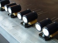
All the chips (LM3875) are mounted on a peice of 2"x1" aluminium bar 12" long.
Right the question:
On top of each chip is the DC blocking cap 2.2uF Evox (glued) and then the two 1000uF electrolitics glued on top of that.
Will the heat of the chip adversely effect the performance of the blocking cap?? introduce distortion??
I have started building a 5 channel slave amp for my AV receiver using the inverted Gainclone topology.
All the chips (LM3875) are mounted on a peice of 2"x1" aluminium bar 12" long.
Right the question:
On top of each chip is the DC blocking cap 2.2uF Evox (glued) and then the two 1000uF electrolitics glued on top of that.
Will the heat of the chip adversely effect the performance of the blocking cap?? introduce distortion??
Elcaps have lower ESR with higher temperatures, but also shorter lifes.
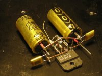
In a class A amp here a bank of local supply decoupling caps is in the line of sight of the main heatsink: something you can feel!
I have covered these caps in aluminium foil to reflect at least part of the IR. This works fairly well, although a more solid barrier spaced a couple of mm away from the caps would be much better still.
Hi Peranders,
Sorry for the spelling in the last post
I am following the cct on this website:
http://www.euronet.nl/~mgw/diy/amps/uk_gainverter_1.html
Sorry for the spelling in the last post
I am following the cct on this website:
http://www.euronet.nl/~mgw/diy/amps/uk_gainverter_1.html
Attachments
peranders said:I
If you have an inverting amp this is waaaay too much.
Way too little, you mean.
2.2uF, 10k ==> 7Hz.
Have a look at the group delay.
My opinion is that I would not epoxy anything to the substrate because it needs thermal contraction and expansion and the epoxy will hinder it....if you must place the cap there then I suggest a high heat silicone but even then I would be reluctant because that also hinders the natural induction of the die substrate to the metal tab
DIRT®
DIRT®
Thanks for the reply Joe, OK a couple of things, the parts are glued with CA and can break apart very easily. The P2P wiring should hold all componants in place, the glue is just for a little bit more mechanical reinforcement. So any thermal expansion or contraction should still be able to take place.
The other thing is that the IC is the TF insulated version
Can you explain this futher??
The other thing is that the IC is the TF insulated version
I would be reluctant because that also hinders the natural induction of the die substrate to the metal tab
Can you explain this futher??
Ok, I didn't exactly understand you, now I do. A plastic capacitors can take rather high temperature but I think it's not so wise to glue an electrolthic capacitors on top of a hot surface. Try at least mount it so it is as cool as possible. Every capacitors get worse when it's hot, no parameter gets better.
Think of this:
85 deg C = 3000 hours
60 deg C = 30000 hours (roughly)
40 deg C = a decade at least
I recoemmend that you use a glue which is somewhat soft, not hard epoxy.
BTW: 2.2 uF as input coupling capacitor is OK.
Think of this:
85 deg C = 3000 hours
60 deg C = 30000 hours (roughly)
40 deg C = a decade at least
I recoemmend that you use a glue which is somewhat soft, not hard epoxy.
BTW: 2.2 uF as input coupling capacitor is OK.
You´re right saying that but at least the capacitance rises slightly with temperature.Every capacitors get worse when it's hot, no parameter gets better.
I repaired so many TV´s with just a hairdryer.
Heat the suspicious cap with the dryer, capacitance rises to original value and the switching supply starts working again.
Then cool it down again to be sure it´s that cap and put a new one in.
But don´t get me wrong here!
We don´t want to heat our caps permamently.
Cheers
Jens
I wouldn´t put it all "above" the chip.
It can get so hot your foil caps probably melt or get slightly brown on the sides and probably also have a failure one day.
Electrolytics dry out relatively fast but if you mount your heatsink vertical I think it´s OK for those.
That´s one I like.
Cheers
Jens
It can get so hot your foil caps probably melt or get slightly brown on the sides and probably also have a failure one day.
Electrolytics dry out relatively fast but if you mount your heatsink vertical I think it´s OK for those.
That´s one I like.
Cheers
Jens
Attachments
- Status
- This old topic is closed. If you want to reopen this topic, contact a moderator using the "Report Post" button.
- Home
- Amplifiers
- Chip Amps
- Cap heating on P2P Gainclone