hello everyone
i am currently plotting to make a high power GainClone (if you can called it that)
i could like to use the basic design that everyone has been using, with possably the addition of bypass caps across the v+ and v- pins on the chip as the power supply caps will not be on the chips themselves.
how should i connect up the input as i would liek to use either 2 or 4 OPA549 chips in parrallel for alot of power.
as i understand it i can use a transformer.. is this just to make the impedance equal? if so would i need one with a 1:4 ratio or could i use one with a 1:2 then followed with another 1:2 after each secondary
i can get hold of a transformer that is written in the catalouge as 1:1+1 is this sutable?
sorry for all the basic questions - i had read though most of the articles and canot find anything this basic.
also would the use of a transformer mean that i do not need imput caps?
thanks for you time. from tom
as i hve just realised that my post didn't really make sense and the only thing it really does is accuratly show my understanding of this.. which isn't much, so i shall try again
i was to make a high power gainclone
i will be using either 2 or 4 OPA549's per channel
i dont know how to sort out the input
i belive people use transformers in the input - is this to make the input impedance higher as i undersand it will drop if i use more then one chip in parrallel?
what type of transformers are sutable for this?
Hi,
Although I haven't seen the schematics you refer to, my initial guess would be that the xformer is to invert the input signal. You simply wire the secondaries in reverse to the primaries. The idea is that there is no lag (I believe) However, you could use two xfomers. One wired in phase, and the other in Anti-phase.
The reason you invert the signal is so that you run one side of the amp in phase and amplify it and the second half of your channel amplifies the anti-pahse (or inverted signal). By the time it reaches your speaker, the signal has a greatly higher amplitude than the single opamp version.
The topology is called Bridged.
Hope this helps,
Gaz
ah.. that makes some sense - i really had decided it was required before looking at what it did.
ok - as all i want is to parallel the chips as im using 8ohm speakers then i suppose i can get away from using a transformer
how can i avoid lowering the input impedance when parralleling chips?
ok - as all i want is to parallel the chips as im using 8ohm speakers then i suppose i can get away from using a transformer
how can i avoid lowering the input impedance when parralleling chips?
Hi Tom,
you can always use a buffer to avoid low impedance.
You should read the AN-1192 for infos.
You should also do a bit of calculating what power you really need and which speakers you´ll be driving as it won´t make any sense to drive an 8Ohm speaker with 4 paralleled opamps.
On the other hand driving a 2Ohm subwoofer it might be handy to have very low impedance output and current capability.
Cheers
Jens
hmm... ok
im just downloading it now (but from a different place as unfortunatly your link dosn't work)
somewhere i have managed to confuse parraleling with bridging..but have no realised that to achive high power i must bridge the chips, not parallel them (or both and use a 4 Ohm speaker insead)
so.. i shall need to bridge and possably parralel the chips apologies for my huge mistake
as this is the case i can sit back for a while and use some of the circuits already posted on the site.
thanks for all that helped me, from tom
im just downloading it now (but from a different place as unfortunatly your link dosn't work)
somewhere i have managed to confuse parraleling with bridging..but have no realised that to achive high power i must bridge the chips, not parallel them (or both and use a 4 Ohm speaker insead)
so.. i shall need to bridge and possably parralel the chips
apologies for my huge mistakeas this is the case i can sit back for a while and use some of the circuits already posted on the site.
thanks for all that helped me, from tom
Not a problem. I'm about to make "Gainclone 3"...which (funnily enough) will be my third. I'm going to make a tube bufferred version. It'll be my first step into the world of tubes.
I'm going to base the aestheics alot around Gainclone 2 (see my WWW) but have a tube out of the top.
Should be good!
Gaz
I'm going to base the aestheics alot around Gainclone 2 (see my WWW) but have a tube out of the top.
Should be good!
Gaz
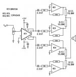
ok - this is probably the design i will use, i had added 2.2Uf caps on each chip to remove DC, also i belive the DRV134 inverts one side which is why all chips work in inverting?
if this is correct and the circuit looks ok then i wil start making it
EDIT: sorry - forgot to wish you good luck with your gainclone.. not that you will need it if you have made two before though
if this is correct and the circuit looks ok then i wil start making it
EDIT: sorry - forgot to wish you good luck with your gainclone.. not that you will need it if you have made two before though
Attachments
I've never built an inverted type - it sounds like they're far more difficult to P2P. Thanks though!
From my understanding, the gainclones produce VERY little DC. You are more likely to intruduce DC offset by not PERFECTLY matching those 0.1R resistors.
Someone correct me if I'm wrong! Looks like you've got a great little project there!
Thanks,
Gaz
From my understanding, the gainclones produce VERY little DC. You are more likely to intruduce DC offset by not PERFECTLY matching those 0.1R resistors.
Someone correct me if I'm wrong! Looks like you've got a great little project there!
Thanks,
Gaz
- Status
- This old topic is closed. If you want to reopen this topic, contact a moderator using the "Report Post" button.
- Home
- Amplifiers
- Chip Amps
- GC prob... oh forget it - brain problems