So over a year later, I've dusted off my soldering iron and finaly got my LM1875 chip amp working. Or had it working.
I was doing a test to see how much the chips would heat up, running at full power for an entire album. But I managed to short the chip to the heat sink when I reached in with my temperature probe. TWICE! The second time killed it.
IIRC, there's an LM1875 variant that has a isolated tab. While it might not get the heat off the die as well as the LM1875, surely this is more then made up for by not having to use the little T washers, a thermal pad and 2 layers of thermal gunk.
Anyway, now I have to order another LM1875 (or 2) and get to work on the case. I haven't fully settled on a design yet. In fact, the more I work on my design, the harder it gets to decide. Now I understand why you all go for rectangular metal boxes: they take very little time to build.
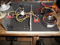
Attached is a pic of what I have so far.
Given that I'm going to be using a wooden box, I'm building a metal box within the box for shielding and mounting. Many screws go through the metal into a sheet of wood underneth. The sheet metal is from an old computer case.
Obviously I have to get a power switch and proper plug set up. And the wires between PSU and the power terminal need to go around the heat sink, not over. I'm tempted to go with unshielded wire from input to amps. The cable is stiff and is part of the reason the PCBs are slopping down from the heat sinks. And don't ask me why I mounted the LM1875s so high up on the heat sink. Thinking about it now, it would make more sense to mount it furthur down. But again, I'm not yet conviced 8x3x1/4 inches of aluminum isn't over kill.
I have half a mind to cut the thing in 2 and have PSU seperate from the amp.
One thing that's slowing me down is that I can only work on this at night and it's not recommended to do wood working in pygamas.
I was doing a test to see how much the chips would heat up, running at full power for an entire album. But I managed to short the chip to the heat sink when I reached in with my temperature probe. TWICE! The second time killed it.
IIRC, there's an LM1875 variant that has a isolated tab. While it might not get the heat off the die as well as the LM1875, surely this is more then made up for by not having to use the little T washers, a thermal pad and 2 layers of thermal gunk.
Anyway, now I have to order another LM1875 (or 2) and get to work on the case. I haven't fully settled on a design yet. In fact, the more I work on my design, the harder it gets to decide. Now I understand why you all go for rectangular metal boxes: they take very little time to build.
Attached is a pic of what I have so far.
Given that I'm going to be using a wooden box, I'm building a metal box within the box for shielding and mounting. Many screws go through the metal into a sheet of wood underneth. The sheet metal is from an old computer case.
Obviously I have to get a power switch and proper plug set up. And the wires between PSU and the power terminal need to go around the heat sink, not over. I'm tempted to go with unshielded wire from input to amps. The cable is stiff and is part of the reason the PCBs are slopping down from the heat sinks. And don't ask me why I mounted the LM1875s so high up on the heat sink. Thinking about it now, it would make more sense to mount it furthur down. But again, I'm not yet conviced 8x3x1/4 inches of aluminum isn't over kill.
I have half a mind to cut the thing in 2 and have PSU seperate from the amp.
One thing that's slowing me down is that I can only work on this at night and it's not recommended to do wood working in pygamas.
Attachments
Last edited:
An observation
DC offset at first turn on was 1.7mV Given the intructions I had, I was expecting 10-20mV. At first I thought something was wrong and it "wasn't working." But plugging in source and speakers and of course it was working.
Not that I'm complaing about 1.7mV, mind.
DC offset at first turn on was 1.7mV Given the intructions I had, I was expecting 10-20mV. At first I thought something was wrong and it "wasn't working." But plugging in source and speakers and of course it was working.
Not that I'm complaing about 1.7mV, mind.
. . .But I managed to short the chip to the heat sink when I reached in with my temperature probe. TWICE! The second time killed it.. . .
For this reason, my next LM1875 group project will be Parallel LM1875 Single Rail. I haven't worked out the details on it yet, but it will be really easy and it won't use any sort of circuit boards. In the case of the little 5 pin chip, circuit boards aren't making anything easier.
Your photo doesn't show heatsinks, but it does have nice big heat spreaders. The missing item is conduction of the heat into the air. Perhaps some U-channel added vertically or some holes added, could increase the effective surface area. Air is not particularly conductive, so a "slick wall" doesn't make much of a heatsink.
In building your enclosure, you might want to allow for an air intake at or near the bottom of the enclosure. And of course, it could use a hot air output at or or near the top of the enclosure. Allowing cool air to enter and hot air to leave, can save diodes, transistors, chips and capacitors from heat damage. Otherwise you have an oven.
Perhaps some U-channel added vertically or some holes added, could increase the effective surface area.
Holes seem counter productive. A 1/2" hole in 1/4" stock is has a surface area of (roughly) 13/16" sq in. But it removes a surface area of (roughly) 6/16". Any other size gains less surface area. In fact, holes bigger then 1" will actually lower the surface area.
U-channels I can get. Would thermal gunk + bolts be better then welded on? I suspect so; the weld would create a small air cap inside.
Part of the goal of my aborted experiment is to convince myself that 2x30w chips will produce as much heat as the huge heat sinks I see used seem to imply it will.In building your enclosure, you might want to allow for an air intake at or near the bottom of the enclosure. And of course, it could use a hot air output at or or near the top of the enclosure.
But now that I think about it more, the goal of a heat sink isn't to absorbe heat, but to get rid of it. And one needs surface area and cooler air flowing over it to achieve this.
Off to revise my plans. Yet again.
(For reference, I have 27v rails.)
Things I discovered this evening
I now have quantum LM1875. It is both fried and OK, I won't know until I measure it.
Tomorrow, time permitting, I'm going to do a listening test with better speakers. And some long term heat tests.
Question: is it useful for heat disipation tests to run the amp without speakers? Is that even safe?
- Having a LED on the PSU is useful if you are the type who plugs the wrong plug into the wall socket;
- No matter how hard you try, eventually ever tool will clutter up on your work surface;
- My test speakers sound really bad;
- At loudish volume, the amp is only drawing 0.07 amps from the wall;
- It turns out that my chip probably wasn't fried.
I now have quantum LM1875. It is both fried and OK, I won't know until I measure it.
Tomorrow, time permitting, I'm going to do a listening test with better speakers. And some long term heat tests.
Question: is it useful for heat disipation tests to run the amp without speakers? Is that even safe?
You have Schrodinger's LM1875, from the same box as his cat. ")
It's safe to run a solid state amp without speakers, but it's not useful for making it warm up or testing power dissipation. Putting power into the load is what causes the output device to heat up. But you can put a high-power (20 watts or more, depending on the output power this thing will give out) 8 ohm resistor, or whatever resistance your speakers are rated at, on each output in place of your speakers to make the chip "see" the same load as the speakers and warm up with that.
It's safe to run a solid state amp without speakers, but it's not useful for making it warm up or testing power dissipation. Putting power into the load is what causes the output device to heat up. But you can put a high-power (20 watts or more, depending on the output power this thing will give out) 8 ohm resistor, or whatever resistance your speakers are rated at, on each output in place of your speakers to make the chip "see" the same load as the speakers and warm up with that.
On Schrodinger's chip, be sure to check for DC offset. The failure mode of chip amplifiers is to send one rail's entire voltage into the speaker, get hot, and yet mysteriously continue playing nicely while the speaker's voice coil burns up.
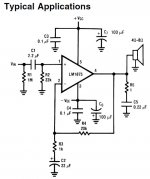
Also helpful in preventing stability related accidents is to install the RF blocking cap per the National Semiconductor LM1875.PDF datasheet. This part promotes stability and is a standard for most op-amp builds, no matter if the chip is small or large. The tiny little cap is a big head start.
http://www.national.com/ds/LM/LM1875.pdf
Also helpful in preventing stability related accidents is to install the RF blocking cap per the datasheet.
I don't see a mention of RF blocking in the datasheet. Do you mean C2, the cap between -input and ground? If so, yes I have it.
Attachments
But you can put a high-power (20 watts or more, depending on the output power this thing will give out) 8 ohm resistor,
I don't have one of those. But I do have the heating element from a cloths dryer. So over heating won't be a problem.
[runs to check resistance]
DVM says 7.7 ohms. But it didn't read it right away, but went from 0 to 7.7 ohms and stayed there. Usable as a dummy load?
I have not managed to locate any twisted wire pairs.
Do you believe in twisted pairs for low loop area?
Do you believe that low loop area is irrelevant to performance?
I don't really know how to answer these questions. I have a lot of cat5e, which is unshielded twisted pair. But I doubt that answers your first question.
As to the other 2... what do beliefs have to do with Hi-Fi amplification? At best, we need reproducable falsifiable phenomena, at worst, subjective interpretation of those phenomena. Belief doesn't enter into it.
RF blocking: Yeah, I looked and don't see anything either. That C2 isn't it, that's "DC blocking" to reduce the DC gain down to 1 to minimize DC offset on the output. The LM3886 data sheet does mention this, though:
http://www.national.com/ds/LM/LM3886.pdf
The schematic on page 6, Figure 2, shows Cc, 220pF, across the + and - inputs to reduce possible RF ("high frequency") problems, as described for Cc on page 8 (and I don't know why they only mention fluorescent lams as a source of electrical noise). Not sure if it would do the exact same thing with the LM1875, maybe others could give an opinion. Putting a 220pF cap across R2 in the circuit you posted in #10 would help reduce RF.
Yes, a clothes dryer heating element of the right resistance (7.7 is plenty close enough) will make a great dummy load for anything under 1,000 watts or so.
For AndrewT's questions, making wires that carry equal-but-opposite currents (such as the transformer primary wires, and each transformer secondary winding) into twisted pairs reduces the magnetic fields (the "loop area") they generate (or for a low-level signal, it reduces the sensitivity to external fields), so there's solid reason to do it (this can reduce some low-level 50/60Hz hum induced by the wiring). His questions may be a bit oblique, but the other posts I've seen from him show a solid knowledge of electronics. I suppose his questions were just an indirect way of pointing these things out.
Last edited:
re: LM1875 RF blocking
I think he means this, from pg 6 of the datasheet:
"Occasionally, current in the output leads (which function as antennas) can be coupled through the air to the amplifier input, resulting in high-frequency oscillation. This normally happens when the source impedance is high or the input leads are long. The problem can be eliminated by placing a small capacitor (on the order of 50 pF to 500 pF) across the circuit input."
I can hear zero hiss or hum from the amp when powered on, no music. Given that the LM1875 has -92dB ripple rejection, I live in a small village and I'm doing my tests in the basement, this isn't suprising.
However, given how solicitous you folks seem about interference, I'll dust off my 'scope and or get a better pair of ears and check.
However, given how solicitous you folks seem about interference, I'll dust off my 'scope and or get a better pair of ears and check.
use your DMM set to 199.9mVdc and set to 199.9mVac to measure the output noises when the input signal is shorted to input ground/return.
Then attach your source (switched off) and remeasure your output noises.
Finally turn on your source but with output signal turned down to max attenuation and remeasure the output noises.
If all of these are <0.1mVdc and <0.1mVac then you do indeed have a quiet system for ordinary sensitivity speakers.
My test source is a battery powered Sandisc MP3 player.
If I stick my ear right up to the speaker, I can hear a very faint hum.
Input shorted to ground: -0.9mVdc 8mVac
Source turned off: -0.8mVdc 9mVac
Source turned on, max volume: -0.8mVdc 9mVac
So it seems I do have an antenna.
Note that I haven't finished my case yet. Far from it. As you can see in the picture in the first post, I only have the back and bottom done.
Your DC values are good and show that the amp is unaffected by the source.
The AC values show a consistent problem.
8mVac is at least 30dB too noisy. It could be improved, when all is corrected, by between 38dB and 40dB. Yes, a total noise target measured with a DMM can be <0.1mVac
The AC values show a consistent problem.
8mVac is at least 30dB too noisy. It could be improved, when all is corrected, by between 38dB and 40dB. Yes, a total noise target measured with a DMM can be <0.1mVac
Your photo doesn't show heatsinks, but it does have nice big heat spreaders. The missing item is conduction of the heat into the air. Perhaps some U-channel added vertically or some holes added, could increase the effective surface area. Air is not particularly conductive, so a "slick wall" doesn't make much of a heatsink.
I disagree, there is no difference between a "heat sink" and a "heat spreader", they are synonymous for the same thing. The conduction of heat from a solid into air is always a challenging problem, regardless of the shape of your heat sink/spreader. What is really important is that you have surface area for the heat transfer to take place. Using fins or some other clever way to increase surface area will increase the rate at which heat is able to be conducted to the air. Unless you are going to mount some sort of fan, this heat transfer will be driven by natural convection and buoyant forces. The amount of heat transfer that takes place is proportional to the difference in temperature between the two mediums. If the air inside your box has no way out, then the air temp will increase along with the heat sink temp and your whole system will eventually overheat. To avoid this, it is critical that you provide some way for cool air to enter the cavity, and hot air to escape. ie, holes above and below the heatsink.
Louis
. . .IIRC, there's an LM1875 variant that has a isolated tab. While it might not get the heat off the die as well as the LM1875, surely this is more then made up for by not having to use the little T washers, a thermal pad and 2 layers of thermal gunk.. . .
You can mount the LM1875 directly to a thick piece of solid aluminum bar stock as a heat spreader and then use the Kapton, Thermal Paste, and Shoulder Washers to electrically insulate the heat spreader away from the heat sink. There is the terminology for a higher performance thermal interface.
- Status
- This old topic is closed. If you want to reopen this topic, contact a moderator using the "Report Post" button.
- Home
- Amplifiers
- Chip Amps
- LM1875 - oh so slowly