Foxyrick, that sounds like it could work. The nice thing about this circuit is simple and easy to work with, frequency and gain adjustment are completely independent, and is tolerant of an imperfect layout.
I recommend you download the zip file of the circuit I posted (you can get TI Tina software here if you wantSPICE-Based Analog Simulation Program - TINA-TI - TI Software Folder), and just mod and tweek it however you want.
Mike
I recommend you download the zip file of the circuit I posted (you can get TI Tina software here if you wantSPICE-Based Analog Simulation Program - TINA-TI - TI Software Folder), and just mod and tweek it however you want.
Mike
Having read this thread I have to say I agree totally regarding tone controls, I miss them badly! Congrats on your design, I think you have contributed something important here. I would like to build it myself at some point and was wondering what type caps you used etc, it may be beyond me as a novice but I would like to have a go. What voltage do the op amps require?do you have a PSU schematic I could check out. Sorry if I'm asking daft questions here.
Cheers
Davy
Cheers
Davy
I had fancy computer software...
I had chance to add boost to any frequency with 0,01 Hz precision
But i cant remember how it was called... damn!
I was able to turn crap speakers into flat response Hi-End ones
The coolest thing was peak of 50dB boost at lower fq witch turned my 12" into 50"
Flat from 20-70 hz, good times...
And now... I hate my computer sound...
Does anybody know where i can find similar one?
I had that dream once too
Personally any of the pc equalizers I have tried made everything worse, things are improving with pc audio, but the pace is too slow for my liking
I want non-invasive tone controls which I can fit in a preamp case so it will also help with my old UK pressed vinyl records with their boosted mid range.
Hi Davy,
Sorry it took so long to reply, I was pleasantly surprized to see this thread come back to life agian.
I'm not reallty into the whole "botique parts" thing, so any good quality components from known to be reputable suppliers is what I generally recommend using. Any decent polypropylene or mylar type film cap is just fine here as long as it has a high enough working voltage, say 25 volts or higher for a minimum, and should be the tightest tolerance you can find, no more than +/- 5% (I buy a lot of 2% to 3% tolerance caps from DigiKey).
As for supply voltage, the usual regulated +/- 15 volt source will work fine here.
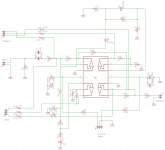
Attched are the schematics for the current version of the tone circuit and an appropriate regulated power supply.
I recommend using either an OPA2132 type Opamp like in the early version, or even better, use one of the LM4582/LME49710 types as in my current version. Those chips have better than average specs, are relatively forgiving of less than perfect circuit layouts, and better than average output drive capability that this circuit needs.


Mike
Sorry it took so long to reply, I was pleasantly surprized to see this thread come back to life agian.
I'm not reallty into the whole "botique parts" thing, so any good quality components from known to be reputable suppliers is what I generally recommend using. Any decent polypropylene or mylar type film cap is just fine here as long as it has a high enough working voltage, say 25 volts or higher for a minimum, and should be the tightest tolerance you can find, no more than +/- 5% (I buy a lot of 2% to 3% tolerance caps from DigiKey).
As for supply voltage, the usual regulated +/- 15 volt source will work fine here.
Attched are the schematics for the current version of the tone circuit and an appropriate regulated power supply.
I recommend using either an OPA2132 type Opamp like in the early version, or even better, use one of the LM4582/LME49710 types as in my current version. Those chips have better than average specs, are relatively forgiving of less than perfect circuit layouts, and better than average output drive capability that this circuit needs.
Mike
Thanks Mike, that's a great looking circuit. I know it can be done on strip board but a pcb would be better for novices like me, wonder If we could persuade someone to make one. I think it's probably beyond me right now but i'm definitely going to keep it in mind for a later project, maybe next year if my budget allows.
You're welcome Davy.
The first one I built was on plain perf-board, wired point to point on the bottom side, and it worked fine with no issues in spite of being a prototype built with junk box parts.
This is actually just one part of a much larger project that I've been working on. I will be posting more related to that in the not too distant future as things progress.
Mike
Mike,
Thanks for posting your tone control circuit. It looks to me like it may be just what I was seeking for my home audio system. I read Dennis Bohn's paper "Accelerated Slope Tone Control Equalizers" (thanks for the link), but my knowledge of filter theory is very basic, so while I admire Mr. Bohn's goals and ideas, I can neither analyze nor judge his circuits and their implementation. The same limitations on my part apply somewhat to your circuit, so I hope you can assist me with answers to a few questions:
1. In the text for your most recent version you mention the LM4582 op amp. Am I correct in assuming you meant the LM4562?
2. Your most recent circuit features bipolar op amps. Your previous version featured the OPA2132 amplifier, an FET-input design. I prefer to use FET op amps where possible to minimize radio frequency interference and to avoid problematic input bias currents. Would either factor be a concern in your most recent circuit?
3. Is there any reason I could not bias the amplifiers into class A operation?
4. Can you recommend a minimum current capability for the power supply, assuming a standard supply voltage of 15V and that the circuit is built as you present it and that there are two channels (left and right)?
5. What is the purpose of the 10 ohm resistors on the op amp power supply pins?
6. Can you recommend a specific rotary switch for your circuit?
7. What are the corner frequencies of the bass and treble sections in your current version?
Thanks for any help you can offer. I look forward to building your tone control.
Last edited:
the tone control circuit from the old Apt preamp was nice also.
a clever design that remove the midrange bump that some don't like in the traditional baxandall circuit.
i posted it here many years ago, maybe search for apt preamp manual (it's a pdf).
i even think the patent has expired by now, so i guess one could also search for the patent.
mlloyd1
a clever design that remove the midrange bump that some don't like in the traditional baxandall circuit.
i posted it here many years ago, maybe search for apt preamp manual (it's a pdf).
i even think the patent has expired by now, so i guess one could also search for the patent.
mlloyd1
Hi Masterjack,
This circuit is an adaptation based on Mr Bohns' designs, primarily the accelerated slope filters.
Answers to your questions:
1) Yep - LM4562 (Stupid fat typing fingers)
2) Either type will work well in this application, I prefer the LM4562 due to it's lower noise.
3) No.
4) Any supply capable of 50mA output or more should be fine.
5) Noise de-coupling, the LM317/337 voltage regulators tend to have noise that becomes more audible, and output has a rising impedance with increasing frequency, I like to filter that out and compensate for as much as possible.
6) I'm trying these out to see if they hold up under use. ConneX 2 Deck, 1 Pole/Deck x 24 Position, Silver-Plated, Shorting (MBB) I modified them to limit travel to 23 steps instead of 24.
7) If my memory serves me right, 100Hz and 8KHz - but they are easily scaled to whatever you want.
Mike
Yeah, one could do something like that, but I prefer old-school/simple rotary switches, digital gives me a headache.An interesting application of your circuit could be realized using digital switches in place of the rotary switches.
Mike
Drive the switches from a simple PIC (PIC18FJ90??) and it would be pretty straight forward to craft something that could be operated from a cheap universal IR remote control or from your wireless network using your IPad or smart phone. Add support for volume using a TI PGA2320 and switching inputs and you have a slick controller that you could run from your recliner.
That sounds like something that many here might like to try, but even if I could do something like that, I prefer the simplicity of rotary switches, and I've been turning knobs for 50+ years, I see no reason to stop now!Drive the switches from a simple PIC (PIC18FJ90??) and it would be pretty straight forward to craft something that could be operated from a cheap universal IR remote control or from your wireless network using your IPad or smart phone. Add support for volume using a TI PGA2320 and switching inputs and you have a slick controller that you could run from your recliner.
Mike
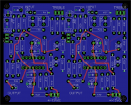
Michael Bean - Interesting circuit! I like the rotary switches. It looks like it would fit on a 80mm x 100mm PC board. This is using a single LME49740 quad chip for each channel on a 4 layer board.
Attachments
Last edited:
- Home
- Amplifiers
- Chip Amps
- A usable tone control