I have built a simple LM1875 based amplifier according to Rod Eliott's schematic, but mistakenly ordered a 22uF electro bipolar as the input coupling cap. I figured it was no problem, except the fact that the amp will reproduce sounds for elephant's ears, but after testing it, i've turned it on, and it worked for about ten seconds with a signal then blew the fuse. Checked everything on the circuit, replaced the fuse, and when it started it it went into oscillation.
I've checked everything again, built it on the same PCB, but with a 2.2 uF cap and another IC, and it works perfectly (the old IC wold still oscillate however).
Just for scientific curiosity, i replaced the input cap with the 22uF on the working amp and voila, another blown IC.
Why did this happen???
When you were "reproduce sounds for elephant's ears" how long did you let this go on? Did the heatsink get hot. Sounds like you were just pushing it to hard. It would also be usefull to measure the power supply rail (rails) while you were pushing it. The larger value cap will pass lower frequency audio which demands more from the chip amp. The power supply was able to put out more than enough poop so the chip took the fall. You could 1. linit the input drive, 2. measure, and if nessisary increase the heat sink size, 3, install some form of potection, like lower value fuse in the transformer primary. Best answer of all is to use the amp withing its limits.
OK - I need to read more before I write. If it is allowed to oscillate, all bets are off. There was feedback between the output and the input which is nessisary for it to oscillate. The higher value cap did not pass the feedback and prevented the problem. Have you got a picture? Perhaps some middle ground value for the cap would be possible with optimized layout. A PC board is highly recomended.
Thanks for the answer. I tested it with no signal and slowly brought up the voltage. I gave it signal with dual 16v dc, the pcb for the amp had a 1amp fuse that blew. The heatsink and the IC were both cold - it was the first thing i checked after the fuse blew. The amp was also connected to speakers, and the volume was quite low.
I figured it might have been pushed too hard, but theoretically the size of the input cap should not matter (it cannot be too large) - as long as the input is within the amplifier's limits, right?
I figured it might have been pushed too hard, but theoretically the size of the input cap should not matter (it cannot be too large) - as long as the input is within the amplifier's limits, right?
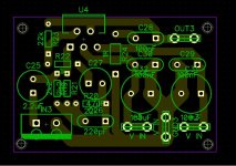
Here's a picture of the layout, it was quicker to get from the PC and it also shows the traces.
Also, it oscillates even with no input signal. The capacitor is connected to the output only through the negative feedback network's ground connection.
The value of 22uF for the amp is not justified at all, a value of 4.7uF would be more than enough to cause no distortion at all at 20Hz. However, since the afore mentioned events, i do not trust my logic anymore and am a little worried about putting 4.7uF in it.
Attachments
Do not connect speaker to any amp that has not be thoroughly tested and measured to check it is not faulty or badly set up.
Do not power up a mains powered project direct from the mains. Use a bulb tester in the Live feed.
Short the signal hot to signal ground for all early testing.
Leave the output terminal without any load in all early testing. There should be a stabilising Network on the output terminal. This can be as simple as an R+C (Zobel)
Thank you for the detailed answer, Andrew.
For early testing the project was powered up using a dual lab power supply, bringing up the voltage slowly. The signal was tied to ground, also the output terminal was left without any load.
The stabilizing network does exist, exactly how you suggested it, and it consists of C28 and R24 in the pcb attached earlier.
I did get the amp working fine, on the same pcb, with a 2.2uF input capacitor, so my question is more theoretical in nature: is there such a thing as a too large input capacitor? (except of course due to the inherent inductance and possibly ESR of larger than needed capacitors)
Also, i really would like to try a 4.7uF, but i am not sure if it won't repeat the same process all over again. :|
I think the input capacitor can be too big. But not for it's DC blocking performance. It's to do with filtering the signal before the amplifier is asked to process filtered signal.
There are a number of threads that have risen recently where this is being discussed.
I bumped into it reading D.Self about 20years ago when as far as I could tell he was the only designer talking about, rather than keeping it secret.
There are a number of threads that have risen recently where this is being discussed.
I bumped into it reading D.Self about 20years ago when as far as I could tell he was the only designer talking about, rather than keeping it secret.
just a note, I asume that you did the layout yourslf, and you are only showing one side. But I like to fill the entire top and bottem side ground with copper in non trace areas. Then connect the two top and bottom side grounds. Not everyone does this, but I find it helpfull to prevent oscillations. You cad software surely has a "fill"" function.
@firechief:
I do usually fill the board for the reason you mentioned, and also to save etchant")
@AndrewT
I have been searching the forum and the net for the negative sides of too big capacitors, but the only thing that came up was the higher impedance, and nothing about effects that may lead to overloading an amplifier.
And of course, diyaudio was the first place i looked, but did not find such threads.
If you do happen to know them, please point me towards them, or at least tell me what key words to look for.
And how could the filtering could have resulted in the IC giving up?
I do usually fill the board for the reason you mentioned, and also to save etchant
@AndrewT
I have been searching the forum and the net for the negative sides of too big capacitors, but the only thing that came up was the higher impedance, and nothing about effects that may lead to overloading an amplifier.
And of course, diyaudio was the first place i looked, but did not find such threads.
If you do happen to know them, please point me towards them, or at least tell me what key words to look for.
And how could the filtering could have resulted in the IC giving up?
I tried with a 47uf cap on the input to see what would happen. It functions as normal but that is what I expected. I sketched a schematic from your board and it seems fine to me although gain may be a bit low for some sources.
If your PS can have current limit set, set it for 500ma for each channel and start at +/- 6 volt rails. Quiescent current should be in the 25-50ma range for each rail. Connect your music source with the volume down. Current should remain about the same. Bring up the volume. Current should gradually rise with the sound, but if it pegs, you may have oscillation.
If your PS can have current limit set, set it for 500ma for each channel and start at +/- 6 volt rails. Quiescent current should be in the 25-50ma range for each rail. Connect your music source with the volume down. Current should remain about the same. Bring up the volume. Current should gradually rise with the sound, but if it pegs, you may have oscillation.
An externally hosted image should be here but it was not working when we last tested it.
http://www.thatcorp.com/datashts/AES7909_48V_Phantom_Menace_Returns.pdf
While this is about mic preamps, a large input coupling cap can hold quite a bit of energy if there is significant DC from the source, but that's most likely not the case here unless you have some faulty tube source.
While this is about mic preamps, a large input coupling cap can hold quite a bit of energy if there is significant DC from the source, but that's most likely not the case here unless you have some faulty tube source.
@johnr66:
Thank you for taking the time to look over my schematic, i will try again with a larger capacitor, not 47uF, but a 4.7uF, with the current limit and measuring the quiescent current to see what happens.
@nereis:
The article was very interesting, and i had never read it before, this could be an explanation for what happened to the IC's, and will check my source for DC.
John,
have a look at your schematic.
Q1.) What do pins 1 & 2 have in common?
A: Both are input pins (+IN & -IN)
Q2.) What is very different in the connection from +&-IN in their routing to the signal inputs?
A:+IN goes through 3 components direct to Signal Hot. -IN goes via the output (R23), via Power Ground, Mixes with Zobel Return and Speaker Return, via common link to R20 before finally making it to Signal Ground.
Q3.) Is there a better way to connect Signal Ground (an input) to -IN?
A: Yes !
Q4.) What do Caps C28, C29 & C30 have in common?
A: They only pass high frequency current.
Q5.) Should the routes of current passing these capacitors have inductance in the path of the HF?
A: No !
Q5.) if the HF through C29 does flow, then where does that current come from?
A: C28 & C30 supply the HF current through the output stage to C29 and to complete the circuit back to the returns of the the decoupling.
Q6.) how do you minimise the inductance of that HF current route?
A: Make the route VERY SHORT !
Last edited:
Andrew, in response to your observations, they are in fact true, but i do not believe that they could lead to the IC being blown, but only to slight hum in the output signal. The reason the PCB is designed as is was the fact that it was intended to be very small, which it actually is.
Also, keep in mind that the amp works perfectly (no audible hum), as long as the input capacitor is no higher than 2.2uF! This is what baffled me in the first place.
On the other side, i have measured the signal source and it puts out a constant 1.6mV DC. Could this be source of my troubles?
The same signal source blew an D-class amplifier in quite a similar way, but at that time i had put it all on the inherent instability of the design, and not the input signal.
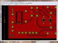
Andrew, I would agree that the paths on his board could be shorter, but they don't seem that bad to me. I use very short paths on my amps. With through hole components, I can't make them much shorter. It may be hard to see in the pic, but the film caps have very short paths and the circuit uses star grounding. The scope shows this amp behaves.
An externally hosted image should be here but it was not working when we last tested it.
On the other side, i have measured the signal source and it puts out a constant 1.6mV DC. Could this be source of my troubles?
The same signal source blew an D-class amplifier in quite a similar way, but at that time i had put it all on the inherent instability of the design, and not the input signal.
The small DC voltage minus the loss through the input divider (resistors) times the voltage gain of the amp means the signal is far too small to blow the amp. The high pass (DC blocking) components mean the offset wouldn't exist for long anyway.
Where did you buy the ICs and components? Some TDA2040s I bought off ebay are suspected fakes. One came with a DC rail on the output. It was put in good circuit. I swapped with good one. Tested with low voltage and current, so it wasn't may mistake. It was a fake Chinese component!
The components were bought at tme .eu, i don't know if they are fake or not, i have no reason at this point to suspect they are, they worked just fine with smaller input capacitors, and look exactly like the other ic's of the same type i have used before.
What are the ic's used for the amp in the picture you have posted? LM1875 or TDA2040?
When you said you have tried with 47uF capacitors, did you ran a simulation or did you built my circuit on the veroboard? Were those capacitors bi-polar electros? (If you did take the time to build the circuit, many thanks for the effort)
After looking at anything that could go wrong, i also stopped at the power supply, it's an old one, using a toroid transformer with two windings and only one rectifier bridge, with the winding ends used as ground reference. When the amp oscillates, even at small currents and without blowing the fuse, the transformer hums audibly. Nevertheless, all measurements on the power supply turned out ok.
Okay, I'll try this again. I posted yesterday and my message vanished when I hit post...
I'm using the TDA2050. It came a few years after the LM1875 and has higher current and voltage swing at a given Vs.
I have the circuit breadboarded. Mine uses more gain and simpler HF filter on the input. I used an ordinary polarized cap. I can try a LM1875. Won't matter. It operates normally.
Your PS design seems fine. I use CT transformer and fullwave bridge to get dual rails. I also use large value filter caps 6,800 uf or better.
When the amp oscillates? What are you doing to cause that?
- Status
- This old topic is closed. If you want to reopen this topic, contact a moderator using the "Report Post" button.
- Home
- Amplifiers
- Chip Amps
- input coupling cap => blown IC