Hello,
I have a Realistic STA-78 amplifier from the 70s. The output transistors are blown. I'm interested in using a pair of LM3875 for the final end.
The original power supply is about 55v after rectification. Can I just take this power, run it over some 10000uf 100v caps and use it to supply 2 LM3875s? What do I do with the center tap?
I already blew a pair of ICs attempting to do this. I have a moderate understanding of power supplies and amplifiers, but I just can't seem to make sense of it.
Any advice would be greatly appreciated...
Thanks,
Nicholas
It sounds like you might have +55 volts and -55 volts, relative to ground. By the way, is it a center tap or are there dual secondaries? Are there two bridge rectifiers or just one?
You need to find out for sure which way it is. Is it: a) +55 and -55 from each power rail respectively to the ground? Or is it 55 volts between the two power rails and +27.5 and -27.5 respectively from the two rails to the ground? A third possibility might be that it's a single-supply, giving just +55 volts and ground.
If you have +55 and -55 relative to ground, then that's too high for the LM3875 and the LM3886, for which the max supply should be +/-42v.
But +/-27.5v should work in the dual-supply configuration of the chip circuit, and +55v should work for the single-supply configuration. Typically, each chip needs +V, -V, and ground connections to the power supply, to run in the dual-supply configuration.
With 4-Ohm speakers, the +/-27.5 would be able to give up to 55 Watts from each LM3875. With 8-Ohm speakers, it would top out at about 37 Watts. See Page 10 of the LM3875 datasheet from national.com.
You might also want to look at the LM3886, which should be able to give 70W into 4 Ohms and 40W into 8 Ohms, with +/-27.5v supplies. See Page 14 of the LM3886 datasheet from national.com.
Last edited:
It sounds like you might have +55 volts and -55 volts, relative to ground. By the way, is it a center tap or are there dual secondaries? Are there two bridge rectifiers or just one?
You need to find out for sure which way it is. Is it: a) +55 and -55 from each power rail respectively to the ground? Or is it 55 volts between the two power rails and +27.5 and -27.5 respectively from the two rails to the ground? A third possibility might be that it's a single-supply, giving just +55 volts and ground.
If you have +55 and -55 relative to ground, then that's too high for the LM3875 and the LM3886, for which the max supply should be +/-42v.
But +/-27.5v should work in the dual-supply configuration of the chip circuit, and +55v should work for the single-supply configuration. Typically, each chip needs +V, -V, and ground connections to the power supply, to run in the dual-supply configuration.
With 4-Ohm speakers, the +/-27.5 would be able to give up to 55 Watts from each LM3875. With 8-Ohm speakers, it would top out at about 37 Watts. See Page 10 of the LM3875 datasheet from national.com.
You might also want to look at the LM3886, which should be able to give 70W into 4 Ohms and 40W into 8 Ohms, with +/-27.5v supplies. See Page 14 of the LM3886 datasheet from national.com.
Thanks for your reply, the power supply shows 55+, 55-, (and a black wire coming from the transfo. going to ground) and then they used 2 35v caps together with the center tap in the middle grounded out like this
55+ 0 55-
----][------][---
(the amplifier is from 1976)
I'm assuming that dual supply means that there are two seperate power supplies (i.e. two bridge rectifiers). Is this true? Would I have a problem wiring 2 LM3875 to the same supply? I looked at the datasheet and it sad that the MAX for the LM3875 was 85volts. I figured that 55-60 would be safe. I had it hooked up, but only got one channel to work. then I altered the power supply and omitted the caps on the V+ and V- to the chips and I think that I fried them. When I tested them, all I could hear was distorted music which cut out sporadically.
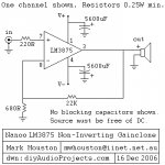
I'm using this schematic by the way...
Is there any way that I could just avoid using the center tap as it is confusing me?
Thank you very much for your time,
Nicholas
Attachments
Thanks for your reply, the power supply shows 55+, 55-, (and a black wire coming from the transfo. going to ground) and then they used 2 35v caps together with the center tap in the middle grounded out like this
55+ 0 55-
----][------][---
(the amplifier is from 1976)
I'm assuming that dual supply means that there are two seperate power supplies (i.e. two bridge rectifiers). Is this true? Would I have a problem wiring 2 LM3875 to the same supply? I looked at the datasheet and it sad that the MAX for the LM3875 was 85volts. I figured that 55-60 would be safe. I had it hooked up, but only got one channel to work. then I altered the power supply and omitted the caps on the V+ and V- to the chips and I think that I fried them. When I tested them, all I could hear was distorted music which cut out sporadically.
I'm using this schematic by the way...
Is there any way that I could just avoid using the center tap as it is confusing me?
Thank you very much for your time,
Nicholas
If you have +55 and -55 and gnd, then the chip spec would have to be 110v or more max supply voltage for it to be OK. The max supply voltage spec is for the voltage between the two power supply inputs, V+ and V-. So 84 V Max means +/-42v max.
You need the ground (center tap), to have both + and - voltages relative to ground. Otherwise, you could only have either +110 and the other side as gnd, or, -110 and the first side as gnd.
Check out how this one works: Power Supply for Power Amplifiers . It's better to use a separate rectifier for each chipamp. But you could run two or more with just one, as long as enough power was available. (But if you wanted _regulated_ dual supplies using only one transformer, then I think the transformer would have to have dual secondaries, instead of just a center tap.)
I looked for a schematic or service manual for your receiver but couldn't find one. Does it, by chance, have an option to run it from 220-240 volts AC? If so, that might cut your +/-55v in half when running from 115VAC. Does the transformer have dual primaries, by chance?
By the way, you do need the caps from the chip power pins to ground, although they don't need to be that large. I would also add some 0.1 uF caps in parallel with the electrolytics, there, close to the chip pins. But don't try to run those chips with +/-55v, anyway.
If you do get the power supply voltages sorted out, I would use the schematic from the official datasheet.
Last edited:
- Status
- This old topic is closed. If you want to reopen this topic, contact a moderator using the "Report Post" button.