I am going to evaluate TDA7293 in single, bridge and parallel operation modes. In this first post, performance of single mode will be presented.
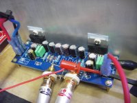
I used a board (two channels configurable for stereo or mono-bridge) purchased from TaoBao. It is powered by a +/- 40 V supply.
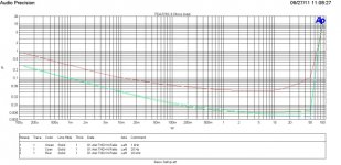
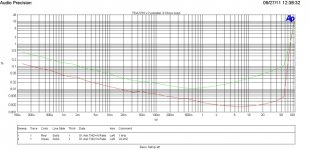
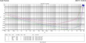
THD vs power for 8 and 4 Ohms are shown here.
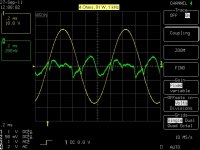
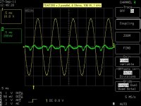
Distortion residual for 4 and 8 Ohms are near rated power are also shown below. Crossover spikes can be seen from the figures.
I used a board (two channels configurable for stereo or mono-bridge) purchased from TaoBao. It is powered by a +/- 40 V supply.
THD vs power for 8 and 4 Ohms are shown here.
Distortion residual for 4 and 8 Ohms are near rated power are also shown below. Crossover spikes can be seen from the figures.
Attachments
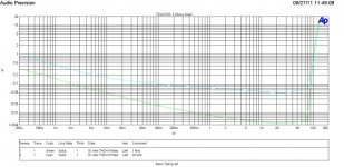
Gain of the board is set to 31 (30 dB).
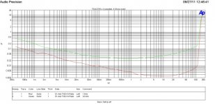
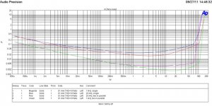
The board is slightly modified for parallel operation. THD vs power for 8 and 4 Ohms load are shown below. Compared to single chip operation, higher output power is obtained. Lower distortion is obtained. On the other hand, distortion at rated output power is similar to that of single chip operation.
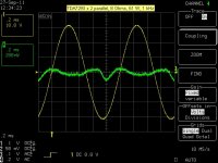
Less crossover spike is seen from the distortion residual.
The board is slightly modified for parallel operation. THD vs power for 8 and 4 Ohms load are shown below. Compared to single chip operation, higher output power is obtained. Lower distortion is obtained. On the other hand, distortion at rated output power is similar to that of single chip operation.
Less crossover spike is seen from the distortion residual.
Attachments
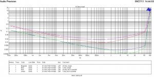
I cleaned up the wiring for parallel operation and run measurement again. THD vs power for 4/8 Ohms of two in parallel is shown in the figure below.
Comparison for single and two in parallel are shown for 4 and 8 Ohm loads, respectively. In all cases shown, parallel operation has lower distortion as expected. It also offers higher output power for 4 Ohms, from 70 W to over 100 W.
PS: Oscillation occurred for high output level in to 4 Ohms load. It was due to the wires connecting bootstrap pins (P12, P6) too close to wire connecting buffer driver pins (P11).
Attachments
Last edited:
Panson,
Thanks for posting all of these results. Very interesting. I wonder if the decrease in distortion will continue as more chip amps are paralleled?
Also, 40VDC rails are getting a little high perhaps... what's the power dissipation like? Can you try 35VDC rails?
The higher levels of distortion that you observe at 20k is typical for this chip amp. It's not a great full range amp because the distortion above 1k rises too rapidly. It should be very nice in a multi-amped system for lower frequency use, however.
-Charlie
Last edited:
Hi Charlie,
I think +/- 40 V rails is fine for paralleling the chips. For single, it would be too high. Yes, a big heatsink is needed.
I think improvement for 4 Ohms will be more or less stop when paralleling up to four chips as LM3886.
I am also thinking to use a configuration "opamp + TDA7293 (slave)". We may have an amp with better performance where output stage in a single package with protection.
Panson
Last edited:
Hi Charlie,
I am also thinking to use a configuration "opamp + TDA7293 (slave)". We may have an amp with better performance where output stage in a single package with protection.
Panson
Hi Panson,
If I understand what you wrote, you want to use an op amp driver instead of one of the TDA7293s as the "master"? Why do you think that would give better performance? Are you sure an all slave configuration will work, e.g. without one of them being the master? What would that gain over other "driver IC + output devices" designs?
-Charlie
opamp's power supply will be the limiting factor?
Good point!
May be Opamp + 7293 (slave) a low-power amp? A headphone amp? Or LME498xx + 7293 (slave) .....
Yes, certainly lower power (or bridged) are possibilities. Would you be able to use your advanced test equipment to find out what phase shift the TDA7293 used as buffer introduces? Its certainly cheaper than the LME or BUF634 power buffers. If its wideband enough it could be a lower cost (and higher power) solution.
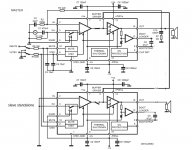
I just made a test confirming that TDA7293-slave can be used solely as an output stage. This is done by not connecting the slave output and bootstrap pins to the master's pins. I still use the master buffer output to driver the standalone slave output stage. The diagram is shown below.
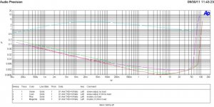
THD vs power for the master and the standalone slave is shown below. The slave-output stage is essentially operating in open-loop (no feedback) mode. Hence, we see very high distortion.
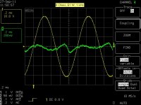
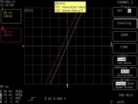
Regarding phase shift of the buffer output stage, I used a 200 kHz tone. Scope connected to master's driver output pin11 and the standalone slave output. The delay due to the buffer output stage is about 0.15 us.
THD vs power for the master and the standalone slave is shown below. The slave-output stage is essentially operating in open-loop (no feedback) mode. Hence, we see very high distortion.
Regarding phase shift of the buffer output stage, I used a 200 kHz tone. Scope connected to master's driver output pin11 and the standalone slave output. The delay due to the buffer output stage is about 0.15 us.
Attachments
Good work - the 0.15uS delay corresponds to a phase shift around 60degrees at 1MHz so its not going to be stable inside an opamp feedback loop. The open loop distortion going up to about 5% looks seriously worse than the other buffers I mentioned but then they don't normally drive 8R. That high distortion is being measured into 8R load which case its understandable I think. What does the distortion look like with 32R load (say as might be from headphones)? I see the unloaded distortion is pretty good ")
I just made a test confirming that TDA7293-slave can be used solely as an output stage. This is done by not connecting the slave output and bootstrap pins to the master's pins. I still use the master buffer output to driver the standalone slave output stage.
...
I guess this is the approach used in some amps being sold on "e-Buy"...
7* TDA7293 In parallel 555W Mono Power Amplifier board | eBay
I believe the board uses master-slave as described in the data sheet. The slave's bootstrap is connected to the master.
How come the pencil got burned? Is its equivalent to an low impedance load? The driving voltage is just +/- 20 V.
Black magic?
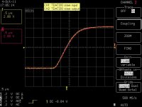
I used a square wave today.
Yes that does look a lot more promising. So the acid test is to put the buffer inside the feedback loop of say a 5534 then play the squarewave through it again. The amount of ringing compared to with no buffer in the loop will give a good indication of how much the delay impacts the phase margin.
<edit> Yeah pencil leads are rather like carbon composition resistors. I think the resistance might depend on the softness (B, HB, H etc) but I haven't verified that. Looks like that 555W amp certainly put lead in that pencil
Last edited:
I doubt whether the higher distortion at 20kHz frequency is audible. Given than the graph of power distribution versus frequency is logarithmic in nature, at 100W the power upwards of 15kHz is going to be under 1W.
The higher levels of distortion that you observe at 20k is typical for this chip amp. It's not a great full range amp because the distortion above 1k rises too rapidly. It should be very nice in a multi-amped system for lower frequency use, however.
I doubt whether the higher distortion at 20kHz frequency is audible. Given than the graph of power distribution versus frequency is logarithmic in nature, at 100W the power upwards of 15kHz is going to be under 1W.
That is not the correct way to interpret the amplifier distortion versus power output graph. Anyway, my point is about the rising distortion above 1k Hz, not just at 20k Hz.
I am not sure where you get your info about power distribution - music does not follow a logarithmic power relationship, it's more like a band concentrated between 100Hz and 2kHz, with power dropping off on each end. This has been documented in published literature and on at least one DIY site I know of...
-Charlie
- Status
- This old topic is closed. If you want to reopen this topic, contact a moderator using the "Report Post" button.
- Home
- Amplifiers
- Chip Amps
- TDA7293 single, bridge, parallel