I was thinking of a cheap and easy way of adding thermal protection with an indication to a LM4780 amp.
I was thinking of using a thermal switch attached to the heat sink, which opens when the temperature reaches it's set level and then closes when the temperature drops back to the reset level.
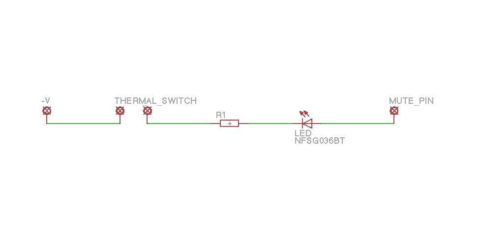
I was thinking of incorporating the power LED through the mute pin by connecting the 'power on' LED, mute resistor and thermal switch in series from -V supply rail to the LM4780 mute pin.
I have a couple of questions.
1) What is the maximum current that can be drawn from the mute pin, as I may need 5 - 10mA (depending on what LED I use). In the pdf file it says:
'Mute resistance set up to allow 0.5mA to be drawn from each MUTE pin to turn the muting function off.'
2) To mute the amp, does the mute pin have to be grounded, or just 'open' from the -V supply? For simplicity, it would be better if it just had to be 'open'
I was thinking of using a thermal switch attached to the heat sink, which opens when the temperature reaches it's set level and then closes when the temperature drops back to the reset level.
I was thinking of incorporating the power LED through the mute pin by connecting the 'power on' LED, mute resistor and thermal switch in series from -V supply rail to the LM4780 mute pin.
I have a couple of questions.
1) What is the maximum current that can be drawn from the mute pin, as I may need 5 - 10mA (depending on what LED I use). In the pdf file it says:
'Mute resistance set up to allow 0.5mA to be drawn from each MUTE pin to turn the muting function off.'
2) To mute the amp, does the mute pin have to be grounded, or just 'open' from the -V supply? For simplicity, it would be better if it just had to be 'open'
Since the internal circuit is the same as the LM3886's you can take the missing data from that datasheet. It shows a Mute Attenuation vs Mute Current diagram that goes up to 10 mA, so you can assume that it is safe to work up to that current.
You could of course connect the LED with an adequate series resistor between V+ and the mute pin. Then you can use all the current you like through the LED, while only drawing 0,5 mA or a little more from the mute pin.
You could of course connect the LED with an adequate series resistor between V+ and the mute pin. Then you can use all the current you like through the LED, while only drawing 0,5 mA or a little more from the mute pin.
Hi pacificblue,
I don't understand why I would connect the LED and resistor from +V to the mute pin! How would this work?

You could also connect the LED to GND instead of V+. One advantage is that the LED resistor can be smaller.
In either configuration the amp will work (with higher mute current) even when the LED goes open circuit. With the LED in series to the mute resistor, the amp would stop working.
Last edited:
Hi pacificblue. What I want to do is to only have the 'power on' LED lit when my thermal cutout is in it's closed state. That's why originally I wanted to put the thermal cutout in series with the LED and the resistor from -V to the mute pin. Therefore if the heatsink gets too hot, the chip mutes and the LED goes off.
As the LM4780 is 2 x 3886 chips I was looking at the LM3886 pdf and it shows the mute pin in connected to ground through a capacitor. So as long as The mute pin can handle somewhere between 5 and 10mA, I should be able to wire it as I want.
Would the chip handle 10mA?
As the LM4780 is 2 x 3886 chips I was looking at the LM3886 pdf and it shows the mute pin in connected to ground through a capacitor. So as long as The mute pin can handle somewhere between 5 and 10mA, I should be able to wire it as I want.
Would the chip handle 10mA?
OK. Just been looking at BrianGTs (chipamp.com) schematic, and he uses a 10K resistor on the mute pin and has the mute pin connected to ground through a 100uF cap.
10K resistor at -30v gives 3mA. I just tested an LED, and 3mA is plenty enough to give a brightness I require, so I think I will try connecting it up like this:
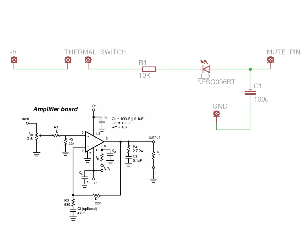
(The black schematic is from the LM3886 manual from Chipamp.com, and obviously the Eagle CAD drawing is my proposed circuit)
The LED shouldn't affect the mute in any way should it?
10K resistor at -30v gives 3mA. I just tested an LED, and 3mA is plenty enough to give a brightness I require, so I think I will try connecting it up like this:
(The black schematic is from the LM3886 manual from Chipamp.com, and obviously the Eagle CAD drawing is my proposed circuit)
The LED shouldn't affect the mute in any way should it?
There is no reason why you should not put the thermostat in series with the mute resistor in my proposal. The LED will also turn on and off accordingly.That's why originally I wanted to put the thermal cutout in series with the LED and the resistor from -V to the mute pin.
Would the chip handle 10mA?
datasheet. It shows a Mute Attenuation vs Mute Current diagram that goes up to 10 mA, so you can assume that it is safe to work up to that current.
")
An answer to post #1 (and post #10)
Quote:
2) To mute the amp, does the mute pin have to be grounded, or just 'open' from the -V supply? For simplicity, it would be better if it just had to be 'open'
Unquote
If the mute pin is disconnected (open circuit) from -V,
then the amp is muted (no sound)
jb74
Quote:
2) To mute the amp, does the mute pin have to be grounded, or just 'open' from the -V supply? For simplicity, it would be better if it just had to be 'open'
Unquote
If the mute pin is disconnected (open circuit) from -V,
then the amp is muted (no sound)
jb74
- Status
- This old topic is closed. If you want to reopen this topic, contact a moderator using the "Report Post" button.
- Home
- Amplifiers
- Chip Amps
- Muting LM4780