Hey all. Let's be frank. I'm a noob. I don't like to be shocked. I don't like things to blow up or even melt. Unless that's the intent, but right now, it isn't.
I purchased and assembled this:
Here's the schematic:
6N11+3866 | Flickr - Photo Sharing!
BB won't let me post the pic for some reason.
The power supply that I have has the following secondary outs:
39/0/39: 21.5/0/21.5: 12.5/0/12.5: 3.5/0/3.5
The amp requires 65v and 8v for the tube power and heater. The bridge rectifiers that I installed can handle 800v, 4a. The original specs asked for 200v, 2a.
I'm making a SWAG that the increased voltage to the tube power will result in approx 109v, ish instead of 91v. I'm certainly not an expert on tubes, but it seems that this wouldn't be too much of a problem unless it sends too much output to the input of the chip. Speaking of which, the coupling capacitor that was recommended was a 3.3uf 100v - but the best match that I could find was a 3.3 400v...
The heater voltage I'm not so concerned about because the 12.5v (instead of 8v) goes through a voltage regulator, an LM7806, whose max input is 35v.
The chip voltage will see 21.5v instead of the 25v recommended.
So my questions are:
Will the increased voltage to power the tube entirely screw something up?
How will underpowering the chip affect stuff?
When I wire the transformer to the amp, there are two spaces for the 65v ac input. I am assuming (should I choose to accept the risk) that I can run 39v to each ac input space as there is no positive or negative ac voltage. If I do this, then I would cap off the ct for the trio, right?
If I run the 12.5 to the heater, then I would run one 12.5v and the ct to the two openings and cap off the extra 12.5, right?
Call me a total noob, I'm just trying not to second guess too much and risk melting things....
I wish i had much to add to this, other than to say that i have purchased one of these boards - but not received it yet - and the seller lamely told me that he doesn't have a schematic or BOM.
A few points:
The chip will be happy with the 21.5v, this will actually be safer if you may use 4 ohm speakers.
You could ignore the 12-0-12 secondary and the center tap of the 3.5-0-3.5 and have 7vac for the heater regulator. likely Close Enough assuming there is enough current on the secondary.
If you stay with the 12.5v to the heater regulator you may need a bigger heatsink there.
I don't know the 6n11 but i hear that it is in the 6DJ8 family. The voltage shouldn't be a problem but someone who is better at tube math than i should take a look at the components around the tube to see if they work well for the tube's operating points at that voltage.
Don't suppose you have a higher rez version of the schematic you could send me, maybe a BOM?
Ericj, I'd be happy to send a BOM and schematic. I don't see an attachment button for sending them to you via pm. If you'd like, I'd send it to an email. Just PM it to me and I'll get it out to you. I had to convert the PDF to jpg and the prog I used did a remarkably poor job.
I didn't know which forum in which to post this as it is a tube buffered chip amp.
I checked the data sheet for the 6dj8, specifically, and it seems that it can handle more juice. I'm concerned how this will affect the input to the chip.
Right now I think that I'm going to run this transformer just to see if it works and get better transformers for it relatively soon.
well, chinese tubes, like russian tubes, can be a bit of a crapshoot wrt what they are "like". I have no intention of buying an actual 6n11 - I may use a 6dj8 or a 7dj8 or a 6n23p or a 6n1p i already have here. Though I'm guessing that the 6n1p won't perform well at such a low b+.
A lot of people use 6dj8 types in the neighborhood of 100v b+. It can go higher but it's not necessary.
There's conflicting info on what the 6n11 is similar to - some say ecc88, some say ecc85. Very confusing. My guess is that some resistor values might need to be adjusted to make it optimal but it will probably "just work". Assuming same pin assignments. This would be a good reason to post in the tube amp forum - maybe someone there is more familiar with the 6n11.
Some asian audio diy forums have english sections specifically so that they can collaborate with westerners, btw, and singapore forums are typically all english. May be more places out there to look for info.
The higher b+ shouldn't affect input to the chip amp if there is a coupling cap between them.
Will drop you a PM with my email address. Thanks!
I used a 6N1P. I didn't trust the 6N11 that I was looking at. I'll see how it works out tomorrow...I'm setting up a test box (literally a box) with the appropriate innards and outtards to hook up a cd player and run it to some speakers. Guess I gotta quit looking at it and see if it will function
What i have heard about the 6n1p is that it does not really sing until it's up over 200v b+. Some run it near 300v which requires some additional complexity since you cannot ground the cathode with that voltage on the plate.
I have 6n1p-ev and 6n6p-i in a futterman-style headphone amp and they sound dreamy and buttery smooth, but that's at 250v b+.
But the 6n1p may work fine for you anyway. And at any rate, having a 6dj8 style tube means that there is a vast variety of similar tubes out there.
Anyway, your 6n1p has a 600ma heater. Your 12v secondary will produce about 16vdc after rectification and filtering, so your regulator will have to drop 10 volts and pass a little more than half an amp. It will run HOT. If the 3.5-0-3.5 secondary has enough current, I suggest starting with that.
Don't lose any sleep over having caps rated for a higher voltage. That is never a problem - as long as it physically fits and is the same (or near) uF, the extra voltage tolerance just means it's physically larger and may have a longer lifespan.
I see your point.
Ignore the 12.5/0/12.5, use the 3.5 x2 so as not to overtax the regulator.
I have some JBL lx300 speakers - not the most sensitive by any means, but they are the best speakers that I have right now unless I go with a 4 ohm MB Quart 6x8 pair that I haven't installed in the car...I think I'll take a chance with the JBLs and see.
When I run a simulation of the power circuit, it looks like 21.5v ac will produce a supply voltage of around 13.9v and 14.9v. Adding the absolute values of the average yields ~ 29v. The datasheet for LM3886 says that this will produce an output of about 41 watts into an 8 ohm load and much more than necessary for a 4 ohm load to be heard...
As far as the tubes - I'm not familiar with Chinese tubes. I've rolled the tubes in several pieces of musical equipment, generally BK Butler stuff and in a few amps, and I've found Russian tubes are good to my ear without spending a ton on some NOS mullard that I'll never use enough to appreciate. At least in the musical gear. So, I went with the Russian version as a start and I'll change it to see if it makes a difference as things go on.
I would be (and am) tempted to ignore the heater rectification and regulation and just run 6vac to wires tacked to the bottom of the tube socket, since i've never had a problem with properly-run AC heaters, but whatever.
Double-check the current ratings for the lower voltage secondaries on your trafo. You may have to use a 7806 and a big heatsink. and maybe a resistor to drop some volts before it gets there.
In any case, keep an eye on it. As long as you are dropping at least 1.2v at the regulator, you are fine. Less than that and the regulator may not be performing well. In which case, it could potentially just be replaced with a power resistor. Heaters aren't tremendously picky.
The thing about 4ohm vs. 8ohm in an lm3886 is that you have to run the 3886 at fewer volts to safely drive 4 ohms. 18-22vac transformers are routinely recommended for 4-ohm lm3886 applications.
As for myself i have a 300VA 25-0-25-0 Antek toroid I plan to use, which means i may not have enough volts on the tube section. I am considering building a voltage doubler into the upper side of the AC section to supply more volts to the tube B+ than to the chip. Since the tube won't be pulling much current this should be fine.
Also you're forgetting that AC voltage is measured as RMS, but after rectification and smoothing you will see peak voltage, less diode drops. Multiply by 1.414 and (probably) shave off a volt for diode losses, and you are in the neighborhood of +/-30vdc across the lm3886.
And we are still making assumptions about transformer regulation, the actual voltage at your ac mains, etc. It could easily be a few volts more than 30.
And we are still making assumptions about transformer regulation, the actual voltage at your ac mains, etc. It could easily be a few volts more than 30.
Last edited:
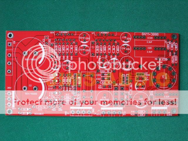
So my board finally showed up.
Curious discrepancies between BOM, schematic, board, and datasheet around R1 and L1.
These are the output bits on the chip amp. L1 is there to prevent RF from feeding back into the amp. The resistor in parallel from it is to assure that the output is never unterminated (e.g. when the amp is producing near-RF of it's own for some reason).
Old BOM and new BOM both agree on 0.22uH, but the datasheet recommends 0.7uH. I guess someone felt that 0.7uH cut out too much of the 'air'? probably harmless. Not arguing with it.
For R1 the old BOM says 10Kohm, the new BOM says 0.15ohm, datasheet says 10ohm.
Like i said, this network is about preventing bad things from happening at high frequencies.
I wonder what values are used by gainclones and the like?
I bought a fully assembled one last year from ebay.
Yet to build it cos yet to find a trafo - one that turns up in a DOA amp in my possession I mean.
Anyway my amp calls for 8V - apparently anythign from 6.3-9 I think and 26-0-26V.
I thought I cant over shoot that by much, has to be 26 ? no ? how much can I put in - advantages if its more ? disadvantages ?
Thanks.
Srinath.
I bought a fully assembled one last year from ebay.
Yet to build it cos yet to find a trafo - one that turns up in a DOA amp in my possession I mean.
Anyway my amp calls for 8V - apparently anythign from 6.3-9 I think and 26-0-26V.
I thought I cant over shoot that by much, has to be 26 ? no ? how much can I put in - advantages if its more ? disadvantages ?
Thanks.
Srinath.
The notes on the schematic say that you can use a 65v transformer for the tube b+ supply or you can use the 54vac from the lm3886 supply trafo, depending on how you configure JP1.
65vac would be better than 54vac. If the 6n11 is truly a chinese 6n1p, 250vac is much better than 65v. Some people run them as high as 350vdc. I think mine sound Really Smooth at 235vdc.
If you have other 6dj8 types on hand, i do recommend tube rolling. I'll give the 6n1p a try but figure i may have better luck with the 6n23p.
Personally i went to antekinc.com and bought a 300va 25-0-25-0 for about $40 and a 10va 6v-0-6v-0 for $10.
If you look at the general advice for use of the lm3886, the highest you want there is about +/-28vac, and the least about +/-18vac if you use a separate transformer to feed the tube plate supply, it shouldn't matter where you fall in that range. The only caveat is that if you intend to drive 4ohm speakers you want to land lower on the voltage scale rather than higher.
Transformers from 150va to 300va are reasonable choices.
I think my choice of heater transformer may have been foolish. For a dollar more i could have had a 9v 25va trafo and had no worries about having enough headroom for the voltage regulator. But i could also just cut the traces that feed rectified 6vdc into the heater and tack a tightly twisted pair of wires to the tube socket pins and have AC heat with no worries. Also a couple 220ohm resistors between each heater leg and ground.
With two 100uf 100v caps and two 1n4007 diodes you can double the upper half of the main transformer. Nowhere on the board for this, but you can air wire it or add a bit of perfboard. I may do this, giving me 75vac on the b+ supply without needing me to get a 3rd transformer for b+.
This should be Just Fine because the tube is unlikely to draw a whole lot of current. Alex Cavalli's "SOHA" series of headphone amplifiers use multiple voltage doubling stages to provide a good b+ to a 12au7 off of a 15-0-15 transformer with excellent results.
Whether or not the resistor network around the tube is ideal for the given volage and given tube is a subject for people better at tube math than i am.
Last edited:
65v, 250v ? I only have 26 and 8v markings on mine.
Where you seeing all the other voltages from ?
BTW is a center tapped 26-0-26 one needed ? Or can we supply the 2 26 inputs with the same 26 and the other one gets the 0 ? Thanks guys.
Cool.
Srinath.
Look at the schematic linked in the first post for where the 65v is.
You either have a separate transformer for tube b+ connected at J3 and then connect pin two to pin three at JP1 or you don't have a separate tube b+ supply and you connect pin one to pin two at JP1.
In either case, "ground" for the tube is really V- for the chip amp supply. The question is whether B+ is V+ or some other voltage.
With tubes, since we are trying to get electrons to jump through a vacuum, more volts is typically better. Most 6dj8 types work ok at 70vdc or so, the 6n1p is reputedly not one of them. I do not know the 6n11 but it has been claimed that it is a chinese 6n1p.
Other than that i should have been more clear. This board was not designed with a 250v b+ in mind. But the 6n1p tube was.
The resistors around the tube and the voltage at the plate determine the operating parameters of the tube. A big change in voltage would necessitate changing the resistor values, and i was never any good at figuring that stuff out. You could start a thread in the tube forum asking about 6dj8 cathode followers.
The chip amp part of the board needs a dual supply - that means you need either a center tapped transformer or a transformer with dual secondaries or two transformers.
Last edited:
OK so the tube alone now will work on if I do 28V - 28 X 2, 56V ... if I were to not modify anything. Yea its warmed by 6.3v ... and 28-0-28.
So you guys are running the tube alone @ 235 - OK I have a very dumb q ...
OK so in my amp my tube runs @ 56. Say I think higher = better, so How would I prevent the tube's voltage feed from getting in the rest of the amp ... so I remove the tune from the socket and run sires to an outboard socket and run it to that and have a huge resistor to prevent it from getting into the amp ?
Then here is stupid Q #2 ... say I wanna try more voltage @ the tube ... cant I run it to the outlet power directly ... 117v ...
Then say I wanna try more ... could I use a doubler circuit to feed it 235 ? Is that how you got your 235 ? Thanks.
Cool.
Srinath.
OK so the tube alone now will work on if I do 28V - 28 X 2, 56V ... if I were to not modify anything. Yea its warmed by 6.3v ... and 28-0-28.
So you guys are running the tube alone @ 235 -
My 6n1p tubes are in another, completely different amp (a headphone amp) with higher b+. Right now my lm3886+6n11 board just has a few resistors in it. build is still in the early stages.
OK I have a very dumb q ...
OK so in my amp my tube runs @ 56. Say I think higher = better, so How would I prevent the tube's voltage feed from getting in the rest of the amp ... so I remove the tune from the socket and run sires to an outboard socket and run it to that and have a huge resistor to prevent it from getting into the amp ?
C20 does that for you. Capacitors block DC, so all the chip amp sees is the peak to peak AC component, which is just a few volts at the most.
Then here is stupid Q #2 ... say I wanna try more voltage @ the tube ... cant I run it to the outlet power directly ... 117v ...
Then say I wanna try more ... could I use a doubler circuit to feed it 235 ? Is that how you got your 235 ? Thanks.
No, very dangerous. You always need transformer coupling.
I do not recommend trying to use this design with a very high B+. Not more than a hundred volts.
All i was saying is that the 6n1p is not typically considered to be very good at lower voltages, and you may have better results with an american or european 6dj8 or ecc88 type.
Which should plug right into this board with no modifications.
Hehe ... 235V is easy, surplus places have those 220V trafo's for euro stuff.
I actullay remembered I have a brick sized one I have been tripping on ...
I also have a 110-55 which can be run reverse for the 235 ... or straight on for 55, sadly its not center tapped.
Cool.
Srinath.
I actullay remembered I have a brick sized one I have been tripping on ...
I also have a 110-55 which can be run reverse for the 235 ... or straight on for 55, sadly its not center tapped.
Cool.
Srinath.
Per this thread:
http://www.diyaudio.com/forums/tubes-valves/197179-help-6n23p-cathode-follower.html
It's suggested to switch R7 and R23 to 200R and R8 and R21 to 10k for 6dj8, 6922, ecc88, or 6n23p with 90v b+ (65vac tube supply).
http://www.diyaudio.com/forums/tubes-valves/197179-help-6n23p-cathode-follower.html
It's suggested to switch R7 and R23 to 200R and R8 and R21 to 10k for 6dj8, 6922, ecc88, or 6n23p with 90v b+ (65vac tube supply).
has it really been 3 years? i totally sidelined this project.
picked it up again recently.
Word to the wise: JP2 was laid out by a moron.
Regardless of the fact that it's not clear which pin is pin 1, the only valid configurations are pin 1 to pin 2, or MAYBE pin 1 to pin 3.
Pin 1 is tied to the ground relative to the B+ supply on the tube section.
Pin 2 is tied to the ground relative to the regulated heater supply on the tube section.
Thus, if you wanted to float the heater, this is where you'd do it. If not, jumper pin 1 to pin 2.
Pin 3 is Vee, that being the negative power rail on the lm3886 section.
Thus, if JP1 is connected 1-2, setting JP2 to 2-3 will short Vee (-32v or so) to 0V.
If JP1 is connectec 2-3, setting JP2 to 2-3 will short Vee (-32v or so) to B+ (+65v or more).
This is retarded. I'm saying that whoever laid these pins out is developmentally challenged. Pin 3 should either not exist or be moved between 1 and 2.
If JP2 is connected 1-3, that shorts ground on the heater supply to Vee, which might make some sense. Particularly if you are using Vcc as your B+
The stupid is strong here. BEWARE!
For the record, pin 1 seems to be away from heatsink side of the board.
Yuan-Jing still sells these boards. The version they are selling now may be a different revision than i have, since it appears to be missing L1 and LL1 in the version they show fully populated. Maybe they fixed this nonsense?
I still haven't heard it. I've populated my board fully but i am considering upping the voltage spec on some of the bypass caps since i was planning a B+ of at least 90v and used 100v rated caps in the 0.1uf positions for some reason.
Here's the schematic and two different BOMs i have:
Attachments
Last edited:
- Status
- This old topic is closed. If you want to reopen this topic, contact a moderator using the "Report Post" button.
- Home
- Amplifiers
- Chip Amps
- 6n11 + 3886 build questions