I'm in the process of planning out an LME49810-based input stage for a triple CFP output stage I have laying around, and before I get to into it I thought I would get a little feedback from those of you with a little more experience with this than I have.
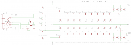
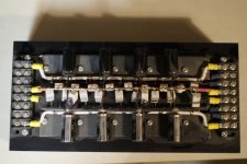
The impetus of the project is having an output stage already built. Everything in the box "Mounted on Heat Sink" is based on Rod Elliot's P68 triple CFP output stage, and I'd really like to be able to use it with relatively few (or no) modifications if possible.
I went with the MJL15034/35 pair as predrivers since I already have them, and the same devices will be used as diodes for thermal tracking. This probably isn't strictly needed as I don't think the predrivers will get very hot, but it should give very good bias control compared to using 1n4004s or no diodes.
Everything else is pretty standard for an LME49810 build. I am thinking about using ~80V rails or so. Is there anything that jumps out at anyone as completely wrong before I pursue this further and start etching some boards?
Attachments
18 To264 devices in the output stage !
What is your load?
Massive driver bias ~180mA.
Don't make the pre-driver bias too low. The MJE need a high bias to get onto the better regions of their performance curves.
Read up on Roender's amp and particularly his output stage. It is very similar and is known to perform well.
As very much of an experiment, what do you think about replacing the BJT drivers with mosFETs?
Wow, 113 pages for Roender's FC-100, it'll take me awhile to read through that. Thanks for the reference Andrew.
I'd like the amp to be stable into 2 ohm with 80V rails, at least for short periods, hence the need for all the devices to stay within SOA at elevated temperatures. This would be intended for sub duties, and I have 64000uF per rail and two 900VA transformers to use in the PS.
I don't think I'd want to switch to a FET output stage. Half the reason for pursuing this project is that I have the drivers and outputs already mounted and wired, while I could make some changes like modifying resistor values switching to a FET stage would require completely rebuilding the output.
Attachments
read again...........I don't think I'd want to switch to a FET output stage.
I said driver stage for the mosFETS, keep the BJT pre-driver and BJT output stage.
Interesting, can you give a quick sketch of what you're proposing? If I understand correctly, you mean for the top half use an NPN pre-driver, FET driver and the NPN BJT outputs, kind of like a BJT-IGBT arrangement?
That wouldn't be nearly as difficult to rewire. What would be the motivation for such a modification, reducing the load on the predrivers?
That wouldn't be nearly as difficult to rewire. What would be the motivation for such a modification, reducing the load on the predrivers?
Some of our very experienced designers claim that FET/BJT gives the best chance for good sound from the output stage.
Using the BJT pre-driver gives the high impedance the previous stage prefers. The FET reduces the current load on the Pre-Driver. The output BJTs are not limited by Rds-on and allows the output to more closely approach the rails.
Optimum ClassAB bias of an 8pair output stage allows a lot of ClassA output for very clean sound and gets very close to the 9pair stage used by one of those designers in his commercial offering.
Last edited:
Based on the schematic, this is not CFP output stage, but emitter follower. CFP is the driver. The output devices should be included in bias-thermal tracking.
Looking at page 516 of Douglas Self's book
Audio Power Amplifier Design Handbook - Google Books
This would seem to be very close to the circuit of figure 6.17b, a CFP-EF. The difference between that circuit and this is that the emitter resistors of the pre-drivers are connected to the output. Rod Elliott whose P68 this is based on said this about it.
It is in the output stage that the power capability of this amp is revealed. The main output is similar to many of my other designs, but with a higher value than normal for the "emitter" resistors (R16, R17). The voltage across these resistors is then used to provide base current for the main output devices, which operate in full Class-B. In some respects, this is a "poor-man's" version of the famous Quad current dumping circuit, but without the refinements, and in principle is the same as was used in the equally famous Crown DC300A power amps.
I guess it would be more accurate to have said this is a CFP with a current dumping follower. At low output levels the main outputs aren't biased on.
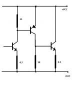
What about a true CFP triple??? Only one 0.7V B-E drop?
I'm designing one now, it has the CFP, but the emitter of the predriver is tied to the OUTPUT through a resistor. Turned it on, but get some oscillation, but still tweaking it out.
That will be an option I'll look to investigate. I really don't have any experience with amplifier design other than simple LM3886/LM4870 designs, so I imagine the learning curve will be steep. I did get my LM chip in though, so once I get my recession buster speakers built I'll get into this project more seriously.
I do like hearing that the output stage should be reuseable though. Other than ljm_ljm, the general consensus seems to be that if properly implemented this should make a serviceable amp.
- Status
- This old topic is closed. If you want to reopen this topic, contact a moderator using the "Report Post" button.
- Home
- Amplifiers
- Chip Amps
- LME49810 using triple CFP output stage