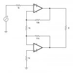
Haven't built it, but have you seen Rod Elliot's page on this topic:
Simplest Ever Bridging Adapter for Amplifiers
-Charlie
Simplest Ever Bridging Adapter for Amplifiers
-Charlie
I hve been use that configuration in all of my Bridged amp simulations when using Circuit maker for years.
I got it out of one of the Opamp Handbooks By Walter Jung.
It works great in sims and I think I used it once in a project, But I don't remember as it was quite some time ago.
jer
I got it out of one of the Opamp Handbooks By Walter Jung.
It works great in sims and I think I used it once in a project, But I don't remember as it was quite some time ago.
jer
I am currently using Rod’ Elliots “Simplest Ever Bridging Adapter for Amplifiers” in my LM3886 amp and I would say it works fine, although I am having two issues with this.
a) Increased hizz due to the poor layout on my pcb’s (I am working on this).
b) A “Bump” to the woofers every time I power up the amp. (any ideas on that would be helpful)
Other than that, dynamics are Stunning and bass is a much better (tighter & deeper) even at low volumes. My speakers have 85db sensitivity and they definitely benefit from that extra power.
Zakman35, Rod Elliotts' version is slightly different from the one I posted, it's a little easier to use with existing amps without modifying them. If you're using the LM3876 or the LM3886 chips, there's an on chip mute function available that you can use to eliminate turn-on thumps. Take a look at the data sheet:
http://www.national.com/profile/snip.cgi/openDS=LM3886
Mike
http://www.national.com/profile/snip.cgi/openDS=LM3886
Mike
I like it. Two suggestions - the 1K resistor in the input isn't necessary (but would be good if you are going to add a rf input filtering cap) and I would use an 11k resistor to ground on the second + input, as this should be closer DC offset wise (and put an 10k to ground input resistance). I don't think it makes that much difference - definitely a build it and see how it flies.
While it's true that the 1k resistor on the non-inverting input isn't necessary, I generally include it in most of my bi-polar input opamp designs to limit the current into the input. From the data sheet: "Prevents currents from entering the amplifier’s non-inverting input which may be passed through to the load upon power-down of the system due to the low input impedance of the circuitry when the under-voltage circuitry is off. This phenomenon occurs when the supply voltages are below 1.5V." For DC offset, the actual resistance should be 917 ohms which is what the inverting input sees (11k//1k), 1k is close enough. And obviously, it's a conceptual schematic, all components aren't shown.
Mike
Mike
Stop! You're making me try to use my brain! Unless you are using a 1k input resistance, the 917 ohm isn't optimal. Best way (IMO) to analyze offsets is to look at input currents, then determine the output required to match the input current. Making the resistance from the inputs to ground works, but in this case the 1k resistor between the two inverting inputs isn't sitting at ground on either end. Another aspect is that since it is bridged, it doesn't matter what the offsets are, but that the outputs sit at the same DC level (but shooting for zero is still probably best) Good luck.
As I stated in my previous post the schematic was presented to illustrate a concept, it's not complete and I didn't do the math for exact values. As for the 1k resistor between the two inverting inputs, because of the way feedback works it is sitting at virtual ground on either end.
Mike
Mike
the virtual gnd is frequency dependent - right at the loop gain intercept frequency
so there is some stability consequence with these decompensated power op amps
you should definitely use higher than the datasheet minimum stable gain - use noise gain compensation if you don't want the higher forward gain at audio freq
so there is some stability consequence with these decompensated power op amps
you should definitely use higher than the datasheet minimum stable gain - use noise gain compensation if you don't want the higher forward gain at audio freq
Last edited:
Virtual ground is not zero volts (it is whatever voltage shows up at the non inverting input so would be based primarily on the input resistors to both non inverting inputs). However, the input bias current is low enough that we are quibbling over millivolts. (or should I say I am just quibbling)
Last edited:
- Status
- This old topic is closed. If you want to reopen this topic, contact a moderator using the "Report Post" button.
- Home
- Amplifiers
- Chip Amps
- Simplified LM3886 Bridge Amp
