So I got three TDA 7266s from the sample order program, and I've tried to wire them according to the schematic, I'm using a 12v-0 power supply(wall wart) and I can't seem to get this thing to turn on, it's getting power to 3 and 13, and it gets power to the stby/mute pins as well.
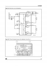
I can't seem to figure out what could be wrong, it's like if it doesn't work at all, could it be that the chips were damaged or something? or am I missing something in the schematic? This is the schematic I used.
I can't seem to figure out what could be wrong, it's like if it doesn't work at all, could it be that the chips were damaged or something? or am I missing something in the schematic? This is the schematic I used.
Attachments
Hi there.
I've had a look at the datasheet here;
http://www.st.com/internet/com/TECHNICAL_RESOURCES/TECHNICAL_LITERATURE/DATASHEET/CD00000203.pdf
where you will find your circuit on page 5.
I would simply switch your circuit on and assuming any heat sink you have doesn't immediately start glowing, check your voltages as follows;
Pin
3, 13...................+12v
8, 9........................0v
1, 2, 14, 15............+6v (use some kind of load if not speakers, i.e. a 1k resistor).
4, 12.....................not sure but should be whatever Vref is. (couldn't find it in datasheet)
6, 7.......................starts at 0v and ramps to +6v in about 0.5 sec. (might be clamped internally, so perhaps won't reach +6v)
If these voltages are correct, then the amp should be running.
I would suggest that to measure 4, 12, you should short In1 and In2 to ground via a couple of 1k resistors, without any other input.
There's nothing fancy about this device, so if the voltages above are confirmed but you still get no output with an input signal applied then logically, the chip is faulty.
Sandy.
Last edited:
Hi there.
I've had a look at the datasheet here;
http://www.st.com/internet/com/TECHNICAL_RESOURCES/TECHNICAL_LITERATURE/DATASHEET/CD00000203.pdf
where you will find your circuit on page 5.
I would simply switch your circuit on and assuming any heat sink you have doesn't immediately start glowing, check your voltages as follows;
Pin
3, 13 +12v
8, 9 0v
1, 2, 14, 15 +6v
4, 12 not sure but should be whatever Vref is. (couldn't find it in datasheet)
6, 7 starts at 0v and ramps to +6v
If these voltages are correct, then the amp should be running.
I would suggest that to measure 4, 12, you should short In1 and In2 to ground via a couple of 1k resistors, without any other input.
Sandy.
Ok, thank you so much, I didn't really know how to test chips of this nature, I'm still learning as I go, as far as heat, no it's cold as ice, all 3 of them are.
Oh yea, stupid question, does an older PC power supply make a good chip amp supply? I do notice they have + - outputs, so I was curious about that.
Oh yea, stupid question, does an older PC power supply make a good chip amp supply? I do notice they have + - outputs, so I was curious about that.
Last edited:
Ok, thank you so much, I didn't really know how to test chips of this nature, I'm still learning as I go, as far as heat, no it's cold as ice, all 3 of them are.
Oh yea, stupid question, does an older PC power supply make a good chip amp supply? I do notice they have + - outputs, so I was curious about that.
No questions are stupid! If you don't ask when you are unsure of something, then you will never learn.
The problem with old PC supplies is that they aren't designed for the job.
They have high current at +5v but only nominal 1A at +-12v, so you wouldn't get much power out.
PC supplies are also quite big, so not really suitable.
Best of luck with the amps.
")
Sandy.
I did have one other question about this chip, can I make it a 14w mono amp? I didn't see a recommended schematic in the list, so I was curious.
Also, how would I go about getting some of those reference boards in the datasheet made? do I just make them myself(try to anyway)
Also, how would I go about getting some of those reference boards in the datasheet made? do I just make them myself(try to anyway
)
Last edited:
I did have one other question about this chip, can I make it a 14w mono amp? I didn't see a recommended schematic in the list, so I was curious.
Also, how would I go about getting some of those reference boards in the datasheet made? do I just make them myself(try to anyway
This chip is ALREADY a bridged amp, so basically no chance of doing what you're suggesting.
Have a look here;
Bridged and paralleled amplifiers - Wikipedia, the free encyclopedia
As to the PCB shown in the datasheet, I reckon you'll have to make it yourself. It's a pretty simple board, so should be easy.
Sandy.
- Status
- This old topic is closed. If you want to reopen this topic, contact a moderator using the "Report Post" button.
- Home
- Amplifiers
- Chip Amps
- TDA7266