This amp is the complementary version of this one:
http://www.diyaudio.com/forums/chip-amps/192934-se-class-regulator-chip-amp-madness.html
Now, the L-R correlation is used to modulate the current source, with L and R having opposite polarities (the loads must also have their polarities reversed).
This version no more qualifies as a true single-ended (it is a sort of hybrid), but it has more output power and even less (simulated) THD than the previous circuit.
An actual prototype will follow soon.")
http://www.diyaudio.com/forums/chip-amps/192934-se-class-regulator-chip-amp-madness.html
Now, the L-R correlation is used to modulate the current source, with L and R having opposite polarities (the loads must also have their polarities reversed).
This version no more qualifies as a true single-ended (it is a sort of hybrid), but it has more output power and even less (simulated) THD than the previous circuit.
An actual prototype will follow soon.
Attachments
I'd prefer the LT1115, for lower distortion. Why have blocking caps (C2) in feedback R's and use a low voltage offset op-amp? I'd bet they are not needed.
I hate cap. coupled outputs but I listened to one for years. Heathkit AA-15. Was OK....
How is the performance at clip? At Current limit? Difficult load (1uf)???
I don't believe LTSpice simulations for a minute of devices like this. Performance is so model dependent and many complex devices are modeled simplistically with many "features" omitted for ease of model generation.
Since you seem so competent, why don't you explain for what precise reason the caps are not needed, and what would happen without them?I'd prefer the LT1115, for lower distortion. Why have blocking caps (C2) in feedback R's and use a low voltage offset op-amp? I'd bet they are not needed.
One advantage of class A amplifiers is that they can be made to tolerate loads ranging from +/-(0->∞)+/-(0j->∞j).How is the performance at clip? At Current limit? Difficult load (1uf)???
This may not be the case for this circuit in this form, but it could be achieved without too much difficulty.
The same cannot be said of your usual chip amp.
I make simulations and measurements, if you care to read the previous topic.I don't believe LTSpice simulations for a minute of devices like this. Performance is so model dependent and many complex devices are modeled simplistically with many "features" omitted for ease of model generation.
The prototype for this particular circuit hasn't been built yet, but it's in the pipeline, and I will report the results.
Last edited:
I can not 100% understand. The circuit shows 2 x 8 Ohm resistors but has only one input.
The sim shows a stereo amplifier being fed by a common input signal.
This is just to illustrate how the circuit works by exploiting the correlation normally present between L and R signals.
I will include a "working" schematic, as in the previous topic, with the L and R channels fully separated.
One input signal should go to the top amplifier, and the other to the bottom one, and the phases of each speaker should be reversed wrt. one another.
I have also problems to understand the circuit.
Wondering first why the phase reversed input is not shown, but you show a full stereo design, not a symmetrical input and bridged output.
Hope your "working" schematic will clear a little bit.
1543
Previous schematic was for sim/test purposes.
Here is the way things are supposed to be connected in "real" use:
Attachments
Previous schematic was for sim/test purposes.
Here is the way things are supposed to be connected in "real" use:
Thanks!
One more question. To make this more usable (not only for headphone amp) it is necessary to multiply the number of regulators.
Is all to do to parallel them and use a 0.2Ohm resistor in each output?
1543
I just basically picked any all-purpose op-amp from the LTspice list.lt1056 is shown on the schematic.
What parameters are important if looking at a substitute opamp?
From my prototypes, I use TL072 or LF353.
This already gives an excellent quality, because the power elements behave like near-perfect depletion-mode MOSFETs having a very high transconductance.
But the ultimate quality will be detemined by the op-amp: 1), because it sets the performance floor, and 2), because its loop gain will correct the remaining non-linearities from the regulators.
In short, the better the op-amp, the higher the performance.
Using a NE5532 would certainly improve things.
Yeah, something of the kind.One more question. To make this more usable (not only for headphone amp) it is necessary to multiply the number of regulators.
Is all to do to parallel them and use a 0.2Ohm resistor in each output?
Of course, the 0.2R will reduce the transconductance of the regulators, but if a number of them are parallelled, this is not too important.
And because the amplifier is class A, and the 0.2R resistance is purely linear, there won't be adverse effects like in a class AB amplifier.
One note of caution:
This version hasn't been physically tested yet, and it is very likely that it also requires a stabilization network, like the previous ones.
It couldC5 & C7 don't have a matching component in the other channel.
Could that go part way to explain the different performance?
That's a possibility too.The inverting amp is quite different from the non-inverting amp. Could that be another reason?
There are other possible reasons:
-Difference of performance/behavior between the 317 and 337
-Middle regulator is a 317
I didn't investigate in details, and it is also probable that the compensations are suboptimal: I simply looked for stability, and did no tweaking for improved performance.
No I didn't try that, but it would certainly work: basically, it's just two amps put side by side with some "electronic glue".Have you tried a BTL configuration?
It looks like it may be very easy to do.
How does this amplifier work
Stereo operation roughly meets that criterion.
Neither bridging nor out of phase operation meet it.
Does the operation of this amplifier depend on the two channels being substantially in phase?Now, the L-R correlation is used to modulate the current source, with L and R having opposite polarities (the loads must also have their polarities reversed).
Stereo operation roughly meets that criterion.
Neither bridging nor out of phase operation meet it.
I just realized that in fact, this version has no advantage in terms of dissipation, regarding the correlation.Does the operation of this amplifier depend on the two channels being substantially in phase?
Stereo operation roughly meets that criterion.
Neither bridging nor out of phase operation meet it.
There is however an advantage for the BOM.
The previous version really had a reduced dissipation for a given output power, thanks to the correlation: the output power with totally uncorrelated signals would have been halved.
If you bridge it in stereo, it is possible, see figure below for the general scheme.Neither bridging nor out of phase operation meet it.
Additionally, for this version, it would be possible to make the bridging "vertically".
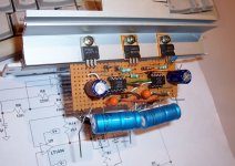
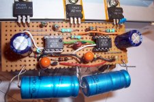
Here are some pics of the latest prototype.
I'll try to make more detailed measurements later.
Attachments
You guys are, wow, unbelievable !!!!
It NEVER came to my mind, a single second, using LM317 regulators as finals in an audio amplifier !!!!
Congratulations ! I like this site !!! I'm new here... (i'm more an RF and PIC guy than audio, but my interest in 20-20k is definitely rising.... my interest in LM3886 gainclones made me joining this, very interesting, site.).
I seriously think that i will learn a lot on audio here !!!!
Thank you !
Here is the circuit working in BTL.
As can be seen, no extra component is required, and it can work in mono.
As I said earlier, this amplifier doesn't do what I had in mind: I had hoped this one would be the Thevenin counterpart of the previous Norton one.
The nice thing about this circuit is its active current load, common to the two channels..
It could even be used by itself to boost a SE amplifier: the amplifier would remains SE (sort of), but with the assistance of the active load.
Attachments
One more thing to say about those amplifiers: they are extremely easy to implement and live with:
Unlike many other class A amps, they tolerate ripple on the power supply, and they are thermally protected thanks to the voltage regulators: if the heatsink is too small, they simply shut down, without fuss or further problems (it happened to me more than once).
And despite their modest output power and performances, they are nevertheless real class A amplifiers, and deliver surprisingly good quality with very small means.
For this reason, they are ideally suited as class A introductory projects: they are on par with any chip-amp for simplicity, but with that little special thing brought by class A and SE.
- Status
- This old topic is closed. If you want to reopen this topic, contact a moderator using the "Report Post" button.
- Home
- Amplifiers
- Chip Amps
- Class A Chip Amp: and now, the complementary version