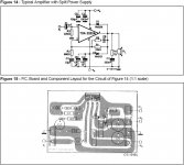
I just built my first working TDA2030 on a 5 hole protoboard. I had some success, but I get very audible distortion mostly at low volumes, but still audible at higher levels. I used the datasheet schematics and values, but I omitted R5 and C8 for the moment.
It's near dead quiet with no input connected, a very slight hum if I put my ear right on top of the speaker. It doesn't run hot at all, a tad warm if no input is connected.
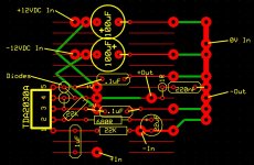
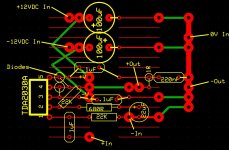
Here's my PCB layout, the green lines with very large pads are wires. Smaller red lines are the PCB copper lines:
and here is a bad pic from my cameraphone of my completed build:
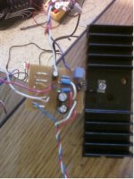
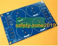
My Power supply consists of a 24VCT 1.5 amp trafo (from the spec sheet)connected thru a rectifier circuit from a LM3886 kit I use regularly with 20000uF per rail (a little much I agree but it's all I have atm). It reads 36.5V total DC power. Heres a pic of the board:
Edit: Noticed my 100uF caps were backwards on the board layout above, and corrected the pic.
It's near dead quiet with no input connected, a very slight hum if I put my ear right on top of the speaker. It doesn't run hot at all, a tad warm if no input is connected.
Here's my PCB layout, the green lines with very large pads are wires. Smaller red lines are the PCB copper lines:

and here is a bad pic from my cameraphone of my completed build:

My Power supply consists of a 24VCT 1.5 amp trafo (from the spec sheet)connected thru a rectifier circuit from a LM3886 kit I use regularly with 20000uF per rail (a little much I agree but it's all I have atm). It reads 36.5V total DC power. Heres a pic of the board:

Edit: Noticed my 100uF caps were backwards on the board layout above, and corrected the pic.
Last edited:
I dont understand what the diodes are for as they may be the source of your distortions.
If you post the schamatic it will be easier to analyze.
Also it looks as though the .1uf cap on the v+ rail is connected to the output instead of the ground as it is a bypass cap.
I just saw this and could be the cause of your distrotion.
As I know what the diodes are for but I don't think that they are necessary.
jer
Last edited:
Also it looks as though the .1uf cap on the v+ rail is connected to the output instead of the ground as it is a bypass cap.
I just saw this and could be the cause of your distrotion.
As I know what the diodes are for but I don't think that they are necessary.
jer
Oops, I didn't do this on my actual PCB, gotta fix the pic. The .1uF is going straight to ground, not output pin #4 as shown. I will fix the board layout pic (again...) and repost new picture.
I didn't think the Diodes were necessary as none of my kits have them, but better safe than sorry. Would save me some space if I removed them tho......
Try it with R5 and C8. I suspect it is unstable if you could see the output on a scope.
I was hoping to avoid this, but perhaps your right. I guess I'll make room by removing the diodes. Thanks guys!
Last edited:
I'm scratching my head trying to figure out what C8 value is. I'm guessing 20K is the cutoff frequency?
From the datasheet:

Google search info:
What is the component value in tda2030a circuit???
I come up with 2040 for R5
C8=361pF
So, 2K Resistor and 390pF cap should be ok, right?
From the datasheet:

Google search info:
What is the component value in tda2030a circuit???
I come up with 2040 for R5
C8=361pF
So, 2K Resistor and 390pF cap should be ok, right?
Last edited:
Remember you are using the cap as a means of increasing the stability margin rather than defining a specific bandwidth. In practice a small value may well be all that's needed, say 22 or 47pf. Without seeing what is actually happening on a scope we have to just best guess it.
Oops, as stated in post #6, I used 390pF. Typo on my part.
Anyway, tried the 30pF with 2K resistor, still sounds a lot worse. I don't have a 22pF, I have a 10 and a 30pF
I think the whole thing is just unstable to tbh...
What prairiemystic mentions about the TDA2030... I've been there myself. These things are surprisingly difficult to get to perform properly with regard to layout and so on. I know you might think otherwise... what could be easier than an IC power opamp...
For any serious audio work you need a scope to really see what's going on.
Would a scope like this suffice?
Pocket Oscilloscope
I just purchased one a week ago, unfortunately I haven't had time to figure out how to use one of these yet (where do I connect it to the amp at?)
I wouldn't like to say if it would show a problem or not. It's obviously very very limited in what it offers. Oscillation and stability problems are often at very high frequencies but there is nothing lost in trying it. Just connect the scopes input across the speaker and observe.
This shows stability issues on "normal" low power opamps,
http://www.diyaudio.com/forums/anal...u-have-checked-see-its-stable-havent-you.html
This shows stability issues on "normal" low power opamps,
http://www.diyaudio.com/forums/anal...u-have-checked-see-its-stable-havent-you.html
I used 2 of these from RS (£1.23 each) no probs at all
Buy Amplifier Accessories TDA2030 PCB audioamplifier,10W 79x63.5mm One Way Circuits M12653 online from RS for next day delivery.
An externally hosted image should be here but it was not working when we last tested it.
Buy Amplifier Accessories TDA2030 PCB audioamplifier,10W 79x63.5mm One Way Circuits M12653 online from RS for next day delivery.
I wouldn't like to say if it would show a problem or not. It's obviously very very limited in what it offers. Oscillation and stability problems are often at very high frequencies but there is nothing lost in trying it. Just connect the scopes input across the speaker and observe.
This shows stability issues on "normal" low power opamps,
http://www.diyaudio.com/forums/anal...u-have-checked-see-its-stable-havent-you.html
Not sure exactly how to do this but is a great exercise for me to learn. Which setting is best for the oscilloscope in my case, AC or DC? Do I disconnect my speakers while doing this?
Leaving the speakers hooked up and running a 100hZ tone through windows media player into the amp, I get a much louder hum after connecting the oscilloscope. This is my results on the DC setting:
![3[1].jpg 3[1].jpg](https://www.diyaudio.com/community/data/attachments/221/221197-b72473b1883289d355f51d67599d5dfd.jpg)
Disconnecting the speaker, leaving all else the same this is what I got:
![2[2].jpg 2[2].jpg](https://www.diyaudio.com/community/data/attachments/221/221195-3cb8c6d50edd4a50816041aa2ad1c480.jpg)
Sorry about the blurry pics......
Edit: I'm just learning how to use this oscilloscope, I can certainly get more detailed readings than posted above. Just let me know what you need (in english, lol) and I'll try to get better pics next time as well.
Last edited:
One thing to check first if you haven't already. Is the output of the amp at zero volts DC with no signal applied. It should be, and to within a few tens of millivolts worst case.
Connecting a scope should have no effect on hum etc so something is wrong somewhere.
Does the hum increase if you just connect the ground of the scope input to the ground of the power amp ? It should make no difference. If it does it seems you might have an earth loop somewhere.
DC coupling should be fine as the output of the amp should be at 0 volts. Any DC offset would move the scope trace up or down or even off the screen.
AC coupling and the trace will always be in the middle.
The output of the amp should remain the same whether a speaker is connected or not. It's common for instability problems to show up when the amp is supplying current to a load and this can be caused by problems in the wiring layout/pcb design as any current can develop unwanted volt drops along conductors. If these alter or modify feedback signals etc then instability can be the result.
One thing to check first if you haven't already. Is the output of the amp at zero volts DC with no signal applied. It should be, and to within a few tens of millivolts worst case.
Connecting a scope should have no effect on hum etc so something is wrong somewhere.
Does the hum increase if you just connect the ground of the scope input to the ground of the power amp ? It should make no difference. If it does it seems you might have an earth loop somewhere.
DC coupling should be fine as the output of the amp should be at 0 volts. Any DC offset would move the scope trace up or down or even off the screen.
AC coupling and the trace will always be in the middle.
The output of the amp should remain the same whether a speaker is connected or not. It's common for instability problems to show up when the amp is supplying current to a load and this can be caused by problems in the wiring layout/pcb design as any current can develop unwanted volt drops along conductors. If these alter or modify feedback signals etc then instability can be the result.
I'm still trying to learn this new Fluke 189, its a sensitive little meter, lol. I'm Currently getting about .090 mV if I shut off all powered items around the meter and amp and step back and don't move or breathe.
Moving my body closer to the meter brings it up to .180 at times. Is this normal?
There is a lot more hum when I touch either probe of the oscilloscope to the positive output of the amp. There is not as much more hum with either probe on the negative, but definitely audible.
Worry about C5, R8 later. There are other problems. You have out ground current flowing in part of the in ground circuit that can cause instability. Redo the board with star grounding. It helps to have input and output leads as twisted pair.
I agree, I was hoping I had a decent star ground, but doing more research shows I need all points to ground to connect at "1" point, if I did my homework right??
Should R3 ground and C2 ground first connect together then go to ground?
Last edited:
- Status
- This old topic is closed. If you want to reopen this topic, contact a moderator using the "Report Post" button.
- Home
- Amplifiers
- Chip Amps
- TDA2030A distortion
