I have read at least two reviews on the 47 gaincard where it was indicated that using two seperate Power Humpty's made the sound "flat, uninvolving" etc compared with just one Power Humpty.
Hence the question: why should the gainclone sound worse with seperate power supplies?
Has it been anyones experience that using two seperate transformers and diode bridges improves the sound quality of the gainclone or is it gainclone lore that one larger transformer sounds better than two seperate transformers? I also saw a post by analog_sa that using a single large (1000VA) tranformer made the sound worse....
I am in the process of building a gainclone and have two 300VA 22v (ac) transformers that I am going to use. So far, the one channel I have built using 1 transformer sounds exceptional.
Thanks for any ideas.
Ryan
saw a post by analog_sa that using a single large (1000VA) tranformer made the sound worse....
the 1000VA i tried with a discrete PP classAB amp... no idea how it would sound with the GC. I seem to think that every amp/speaker combination has an optimal transformer/cap. Very difficult to draw any meaningful conclusions unless you have transformers identical in every respect but VA. Of course such transformers do not exist - variations in VA will bring along variations in many other parameters. I resist the temptation to order a whole lot of different (core types and sizes and wound for different flux densities) transformers and pick up the best sounding
") but for a manufacturer like Peter Daniel this would be quite feasible.
but for a manufacturer like Peter Daniel this would be quite feasible.I'm no expert, but perhaps a sound system sounds better with a little crosstalk. I might get hammered for saying that, but its just a thought. With two seperate transformers, the crosstalk has got to be very small compared to with one. I think since these chips have a very high PSRR anyway, so maybe the effects are basically nill.
Pete
Pete
Hi
Ryan
My gainclones have evolved from a single Tx to this.
I would hardly say a single Tx was better,let alone without a buffer.
Peter
http://www.petemoore.pwp.blueyonder.co.uk/music/
Ryan
My gainclones have evolved from a single Tx to this.
I would hardly say a single Tx was better,let alone without a buffer.
Peter
http://www.petemoore.pwp.blueyonder.co.uk/music/
Attachments


Hi
Very true the project didn't come cheap
BTW the GC's are powered using Thorsten's ultimate supply (2 Tx per channel)
Each Tx is 250 VA 40Volt secondries,primaries are series wired to give 20V on UK 240V mains..Other Tx are for buffer and GC timer delay to allow tube to pre-heat
Peter
Very true the project didn't come cheap
BTW the GC's are powered using Thorsten's ultimate supply (2 Tx per channel)
Each Tx is 250 VA 40Volt secondries,primaries are series wired to give 20V on UK 240V mains..Other Tx are for buffer and GC timer delay to allow tube to pre-heat
Peter
Hi
Ryan
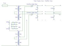
Here is the schematic...
Thorsten stated thus..Who am I to argue
Series connection halves the flux in the core. Less noise, better efficiency. The transformer manufatcurer could have used more turns.
The capacitors AC couple the transformer, so the few 100mV DC on the mains which are common cannot cause DC current to flow and hence the core is not already partially saturated with DC. The transformer manufacturer could have used an airgap. The Diodes BTW protect the Cap's from excessive voltages.
The opposite winding start orientation effectively cancels any leakage between primaries and secondaries, this is known as larger common mode rejection, the transformer manufatcurer could have used shields and wound the transformer symmetrically.
So, in effect we are fixing cost accountant designed mains transformers so we can get away using off the shelf parts. It's nearly as good as a seriously custom wound C or R core transformer....
Peter
btw. I used single Mur860 Diodes not the dual as shown.
Ryan
Here is the schematic...
Thorsten stated thus..Who am I to argue
Series connection halves the flux in the core. Less noise, better efficiency. The transformer manufatcurer could have used more turns.
The capacitors AC couple the transformer, so the few 100mV DC on the mains which are common cannot cause DC current to flow and hence the core is not already partially saturated with DC. The transformer manufacturer could have used an airgap. The Diodes BTW protect the Cap's from excessive voltages.
The opposite winding start orientation effectively cancels any leakage between primaries and secondaries, this is known as larger common mode rejection, the transformer manufatcurer could have used shields and wound the transformer symmetrically.
So, in effect we are fixing cost accountant designed mains transformers so we can get away using off the shelf parts. It's nearly as good as a seriously custom wound C or R core transformer....
Peter
btw. I used single Mur860 Diodes not the dual as shown.
Attachments
Well, one advantage I found when I used two transformers is that if I wired their primaries correctly, the hum picked up by the source cables reduced drastically. Both primaries were in parallel, but swapping the leads of one primary reduced the hum. I guess this is leakage flux cancellation, as peteM mentioned. (BTW, this was for EI transformers, I don't know if two torroidals placed close by would cancel their leakage flux)
- Ashwin
- Ashwin
PeteM
Did you actually listen to all stages of 'improvement' or did you just build it as 'ultimate'? What i mean is did you compare half flux to a single transformer and dc-blocking to no dc-blocking?
I also intended building a similar supply but the half flux setup sounded distinctly more lazy. As it probably should have. The flux may be half but the dc resistance of both primaries and secondaries is doubled and the regulation halved.
Hi
Analog_sa
No i didn't listen to this amp directly.
I have built several chip amps for a friend,then decided to go full bore with my own.
Now if i compared side by side now there really isn't any contest,as good as a chip amp may be a basic GC on my setup sounds exactly that "basic" even if i bypass my valve buffer.
I do not hear a "lazy sound" infact the bass is more controlled with the ultimate supply,better extension and sounds quicker..
I be honest I have not bypassed the DC blocker,but I have powered both monoblocs from from half of the supply.Still it sounds better than my friends GC on dual 160VA Tx (one per channel).
YMMV of course..I can only express what i hear and others in my room..ect..ect..
Stacked against my now sold MF A3 amplifier the hybrid GC is an all win combo,even against my 2A3PP I prefer the hybrid GC,maybe not so warm in the midrange but better all rounder.
http://www.petemoore.pwp.blueyonder.co.uk/music/
http://www.petemoore.pwp.blueyonder.co.uk/music/2A3 PP.jpg
Peter
There seem to be some missing connections on this schematic.PeteM said:Hi
Ryan
Here is the schematic...
Thorsten stated thus..Who am I to argue
Series connection halves the flux in the core. Less noise, better efficiency. The transformer manufatcurer could have used more turns.
The capacitors AC couple the transformer, so the few 100mV DC on the mains which are common cannot cause DC current to flow and hence the core is not already partially saturated with DC. The transformer manufacturer could have used an airgap. The Diodes BTW protect the Cap's from excessive voltages.
The opposite winding start orientation effectively cancels any leakage between primaries and secondaries, this is known as larger common mode rejection, the transformer manufatcurer could have used shields and wound the transformer symmetrically.
So, in effect we are fixing cost accountant designed mains transformers so we can get away using off the shelf parts. It's nearly as good as a seriously custom wound C or R core transformer....
Peter
btw. I used single Mur860 Diodes not the dual as shown.
Hi
Protos
For some reason the picture wouldn't resize without the loss..
But look here
http://www.petemoore.pwp.blueyonder.co.uk/music/
Analog_sa
Thats not a problem but it will have to wait until the weekend.
Peter
Protos
For some reason the picture wouldn't resize without the loss..
But look here
http://www.petemoore.pwp.blueyonder.co.uk/music/
Analog_sa
Thats not a problem but it will have to wait until the weekend.
Peter
Hi, i'm a newbie to ampbuilding but I'm following the chipamp and GC forums quite often.
After I've finalised my new loudspeakers (soon) I'm looking for an amp project and selected to build myself a gainclone
I've noticed that the powersupply on the schematic above has a VA rating in excess of 1000 VA where the original gaincard seems to work fine with 170 VA.
I was already designing with two separate PSU's of 120 VA each (so 240 VA total) The 120 VA rating just fits in the housing that i designed for it and I am a little puzzled by the VA ratings that I see in this tread.
Is it possible to use 2 120 VA transformers or is this a definite no no?
Although my speakers are approx 89db i do not want to drive them to very high levels (they are impedance compensated and should not be that difficult to drive)
n.b. I've designed two options for housing and both are limiting the size (diameter) of the transformer. One is standard alu boxes and the other is made of stainless steel piping (4" and 3") or tubing. Guess that would make it a tube amp but-not-as-you-know-it
indoubt said:Is it possible to use 2 120 VA transformers or is this a definite no no?
[/B]
Hi,
My TGC works OK with 180VA for both channel.
IMHO, 2x120VA is just fine.
Regards
- Status
- This old topic is closed. If you want to reopen this topic, contact a moderator using the "Report Post" button.
- Home
- Amplifiers
- Chip Amps
- Why should a gainclone sound worse with seperate transformers?