I have a Klipsch Promedia 4.1 Sub that I want to use as a home theater sub. I have repaired the power supply and upgraded the wattage on the resistors to fix the flaws in the design. The sub runs in class D and doesnt sound to bad for an entry level setup.
The system origionally had an external pre-amp based on op-amps. I wanted to create my own pre-amp loosely based on the origional design with some improvements. My idea was to add controls for low and high pass filters to add some tuneability to the sub.
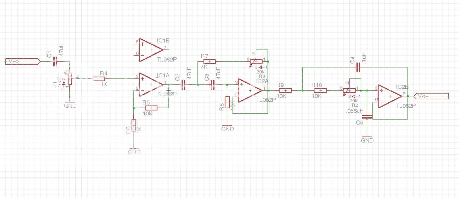
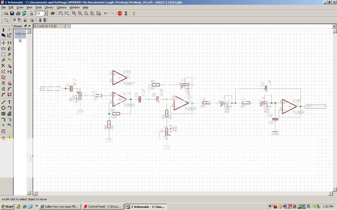
My initial idea uses a 10x gain with 2 saleen-key filters. This may not be the best approach so I am requesting input here. I dont need anything too complicated or fancy. This current schematic has the following specs:
High-Pass - 20-50Hz
Low-Pass - 120-200Hz
Please have a look and provide input.
The system origionally had an external pre-amp based on op-amps. I wanted to create my own pre-amp loosely based on the origional design with some improvements. My idea was to add controls for low and high pass filters to add some tuneability to the sub.
My initial idea uses a 10x gain with 2 saleen-key filters. This may not be the best approach so I am requesting input here. I dont need anything too complicated or fancy. This current schematic has the following specs:
High-Pass - 20-50Hz
Low-Pass - 120-200Hz
Please have a look and provide input.
I'm not too good with actual audio theory, but perhaps you would take interest into something like this?:
Subwoofer (12HZ-48HZ)+(28HZ-112HZ) preamplifier board | eBay
Controls crossover, phase, volume and more.
Decent value considering the cost. Components are actually decent, and don't appear to be knock offs.
Subwoofer (12HZ-48HZ)+(28HZ-112HZ) preamplifier board | eBay
Controls crossover, phase, volume and more.
Decent value considering the cost. Components are actually decent, and don't appear to be knock offs.
I like the simplicity of a completed board but theres 2 problems.
1 The gain is not specified
2 The low pass is a little low for the sub I am using
I could modify the components to my specs but if I am going to do that I might as well just make my own PCB. I am very good with Eagle schematics and PCB's.
I am more interested if my choice of filters is appropriate and the method that I am using to adjust them. Thank You for showing me that alternative.
Still looking for some input as far as my circuit choice.
can you look at the gain and phase on the output of each of the active filters?
If you can, set the VRs to lowest value then to highest value and compare the two sets of curves.
You will find that using single VR in each filter that you are changing the frequency and the Q (roll-off shape) for both filters.
If you want to hold Q at near the same value throughout the range of adjustment you must use a ganged pot for the adjustment of both parts of the filter resistors.
Do you need to sum the bass from two channels (or more) to feed a single bass amp & speaker?
If so then use an MFB active filter.
It has gain and filter frequency and Q all set separately as well as the ability to add two or more signals together without interfering with the stereo separation of the remainder of the audio signal.
Last edited:
The input is just going to be a simple LFE output from my Yamaha reciever. I am following what you are saying about the ganged pot. I will update the schematic so that the resistance of R9 and R10 are both summed with pots.
Is it recommended to add an adjustment for phase? I still have a free I/O from one of the op-amps.
Is it recommended to add an adjustment for phase? I still have a free I/O from one of the op-amps.
For volume, Log.
I believe you'll want linear for things like phase, crossover...though I could be totally wrong on that.
Links?
Mouser and Digikey stock tons of pots, from cheap to really expensive. You can also get some more "exotic" pots from other websites. Depends on what you are after. Mouser has Alps and Bourns which are nice.
Stage 1
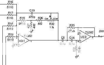
Stage 2
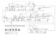
So I am working out the final details on the preamp that I am trying to create and I have run into a few questions.
The schematics above are the actual origional preamp. From what I gather this is what happens.
1 - Volume level is sent from the pot to the gain stage.
2 - Gain is variable adding another level control
3 - High pass filter
Cut-off frequency
fc = 41.5300501346[Hz]
Quality factor
Q = 0.699321882176
4 - Another gain/buffer
5 - Low pass filter
Cut-off frequency
fc = 59.6817235356[Hz]
Quality factor
Q = 0.741334463644
I find it odd that the frequency range is so narrow and that Q is not maintained. I also have no idea how to calculate the gain in the first stage. I have never seen a circuit like that before. Also why does it appear that the signal is amplified 2 times and inverted 2 times? Is it ok to have variable gain based on opamp feedback or prefered to have constant gain? Are the filter caps on the gain stages really necessary?
I have a feeling that the first gain stage is some sort of method to obtain high gains with low value components....maybe to reduce DC offset? I breadboarded a simple opamp gain stage and the sub didnt start to sing until about 50x gain
I am also considering adding a phase control 0* to 180*
Would my proposed circuit be an improvement?
Both filters are 2nd order 12dB/Oct
Q maintained at .5 which makes the filter 'sub-Bessel' (Values can be changed
if Butterworth (.707) is more prefered)
Sorry for all the questions. I just want to try and understand what I am doing vs just slapping something together. Plus I want this thing to sound good too.
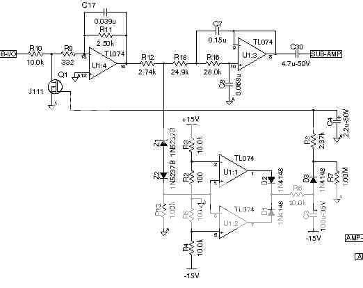
I have been using the origional design as well as this http://lcaudio.com/pdfs/subfilter.pdf as a guide. I don't need auto on/off and would prefer to not have boost or Q adjustments. Volume(and or Gain), Low pass and maybe phase are all I want. I am going to update the schematic and set the high pass at 40Hz 12dB/Oct
Stage 2
So I am working out the final details on the preamp that I am trying to create and I have run into a few questions.
The schematics above are the actual origional preamp. From what I gather this is what happens.
1 - Volume level is sent from the pot to the gain stage.
2 - Gain is variable adding another level control
3 - High pass filter
Cut-off frequency
fc = 41.5300501346[Hz]
Quality factor
Q = 0.699321882176
4 - Another gain/buffer
5 - Low pass filter
Cut-off frequency
fc = 59.6817235356[Hz]
Quality factor
Q = 0.741334463644
I find it odd that the frequency range is so narrow and that Q is not maintained. I also have no idea how to calculate the gain in the first stage. I have never seen a circuit like that before. Also why does it appear that the signal is amplified 2 times and inverted 2 times? Is it ok to have variable gain based on opamp feedback or prefered to have constant gain? Are the filter caps on the gain stages really necessary?
I have a feeling that the first gain stage is some sort of method to obtain high gains with low value components....maybe to reduce DC offset? I breadboarded a simple opamp gain stage and the sub didnt start to sing until about 50x gain
I am also considering adding a phase control 0* to 180*
Would my proposed circuit be an improvement?
Both filters are 2nd order 12dB/Oct
Q maintained at .5 which makes the filter 'sub-Bessel' (Values can be changed
if Butterworth (.707) is more prefered)
Sorry for all the questions. I just want to try and understand what I am doing vs just slapping something together. Plus I want this thing to sound good too.
I have been using the origional design as well as this http://lcaudio.com/pdfs/subfilter.pdf as a guide. I don't need auto on/off and would prefer to not have boost or Q adjustments. Volume(and or Gain), Low pass and maybe phase are all I want. I am going to update the schematic and set the high pass at 40Hz 12dB/Oct
You can modify Q on Sallen and Key circuits by varying the gain of the opamp - K (the gain) is 3 - 1/Q for a circuit with both Rs equal and both Cs equal. For Q = .5, K = 1 : for Q= .7 , K = 1.59. Reference here (there many more references if you search.)
I actually had that site already bookmarked and was using it as a refrence. Thank You though. Any idea as to how the origional gain is calculated? I value any input on the other questions as well. Thank You
i can't read clearly but both input opamps appear to be inverting.
The gain of an inverting stage like that is Rfb/Rs
Rfb = 2.50k?
Rs = 10.0k? + 332r + Rs (of source equipment)
Gain is ~ 2.5times (~+8dB) but will vary with different source components and with different source impedances eg capacitor coupling will vary the gain with frequency. You really do need a well buffered output stage in your source equipment to ensure that the 10k swamps the variations in cables and sources.
The upper inverter has a compound feedback arrangement. I don't have the skills to analyse that for you. I could research it, but I leave that as your homework.
Using WYE to Delta conversions I found the total resistances for the first gain segment to be 7281/11385
This turns out to be a gain of 1.42/2.22
Those gains seem low to me so can someone check my math
x---R1---o---R2---y
.............|
............R3
.............|
.............z
R1=6800
R2=482 & 10482 Low Gain/High Gain (Potentiometer)
R3=482
Delta Converison
Ra=R2+R3+R2*R3/R1
Rb=R1+R3+R1*R3/R2
Rc=R1+R2+R1*R2/R3
After delta conversion
Rxy=(Ra+Rb)*Rc/(Ra+Rb+Rc)
Last edited:
I actually had that site already bookmarked and was using it as a refrence. Thank You though. Any idea as to how the origional gain is calculated? I value any input on the other questions as well. Thank You
Start with equation 6. (Q of generalized sallen and key) Then make all the Rs the same, and all the Cs the same. (r1=r2, c1=c2) and it reduces to Q = 1/(3-K)
that final 10uF capacitor is the DC blocker to prevent damage downstream if something goes wrong with this unit or in a prior stage.
10uF is quite large and can drive good extended bass into >=10k input of the next stage. It cannot drive extended bass into the 4k7 that is fitted on the output.
If you know the Rin of your amps then you can scale that 10uF to an appropriate value to maintain or curtail the lowest bass signal. Multiply the C value in Farads by the resistor value in ohms to arrive at the RC time constant in seconds for a passive RC or CR filter, provided Rs= zero ohms and Rload is near infinity (>4M7).
Aim for ~100ms for extended bass in a home system. 10uF & 10k = 100ms 1uF & 100k = 100ms. Cutting that bass filter by an octave or even two, is preferred by some builders/listeners. Worth trying RC time constants of that bass filter in the range from 10ms to 200ms. PA generally does not try to reproduce extreme bass and they use filters quite a bit higher, 5ms to 20ms are probably quite common. They also tend to use active filters with 2 or more poles to protect their equipment from damage.
Note that the input is filtered with 47ms (@ min volume). Increasing volume to maximum, changes that bass input filter to ~15ms.
As the operator turns the volume up the bass is progressively more filtered.
Once that extended bass is thrown away at the input you cannot get it back by using extended flat response elsewhere.
The fact that the designer (LC Audio) has chosen >=15ms @ input and <47ms @ output tells me this bass filtering system is not intended for home listening. It is more likely targeted at a PA or Disco duty.
In summary, that 10uF could be a value between 470nF and 22uF. Choose to taste. Select a film cap if you can fit it into the case and it can fit your budget.
Last edited:
- Status
- This old topic is closed. If you want to reopen this topic, contact a moderator using the "Report Post" button.
- Home
- Amplifiers
- Chip Amps
- Help with DIY Sub Pre-Amp