I have max power tested amplifiers using those fuses and find they never blow during testing.
The heating effect of music waveforms can never be as high as a max power test, so the fuses should never blow during normal and silly party operation.
For those reasons the lower value fuses using Quasi's rule may be better for even closer rating of the fuse to the duty.
BTW,
33Vpk into an 8ohm speaker can only be had from a supply around +-38Vdc. You should never build a 4ohm capable chipamp using +-38Vdc supplies.
I have max power tested amplifiers using those fuses and find they never blow during testing.
The heating effect of music waveforms can never be as high as a max power test, so the fuses should never blow during normal and silly party operation.
And I'd never doubt your expertise.
BTW,
33Vpk into an 8ohm speaker can only be had from a supply around +-38Vdc. You should never build a 4ohm capable chipamp using +-38Vdc supplies.
That's the point, I might have missed to mention it, but I only have access to 18-0-18 toroids. So for any impedance pkV will be 25.5V. So rather than calculating with the maximum continuous power rating of the AMP I'd rather start with my pkV and impedance and look at I and P afterwards. This won't protect the AMP (with 162W peak theoretical output) but that's what spike is for anyways. And it won't blow the fuse for any power-peaks.
(I am not trying to argue experience here.)
cheers,
hurtz!
Are you sure this is an improvement?I added 100nF caps across the diodes to decrease transformer noise
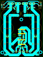
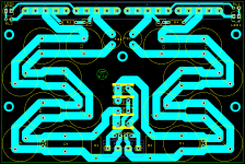
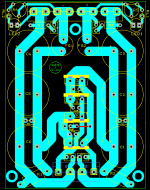
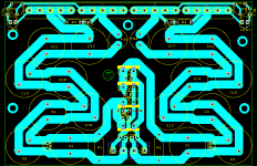
Why not use copper pours (areas) instead of the serpentine traces.
To increase RC-filter characeristics.
AndrewT said:Are you sure this is an improvement?
Well I've read about it on esp which so far never disappointed me, and from the wiring they are optional. I hope I can measure a difference...
cheers,
hurtz
Yet one more question about the secondary fuses, we concluded that the two secondary fuses should be ~2/1.6A for 8r0 speakers. But isn't this the calculation for just one speaker/amp?
Yet twice the ampere rating for two speakers does seem a little bit high. Maybe times sqrt(2)? (And sqrt(5) for 5? :-D)
cheers!
hurtz
Yet twice the ampere rating for two speakers does seem a little bit high. Maybe times sqrt(2)? (And sqrt(5) for 5? :-D)
cheers!
hurtz
So here are some news, the latest revisions have been produced and tested. (PSU+ v2.7/AMP v6.3)
In this design the board is fully populated, including Cd with 330pF, and the new 100nF capacitors across the diodes on the PSU+.
Not included is the 47pF capacitor across the rca inputs.
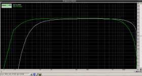
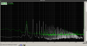
Attached you will find the rmaa test charts, comparing the older [AMP v5.9/PSU+ v2.2] with the new one. Please ignore any stereo-realted data, I only tested one amp with a Y-cable (I had to use rmaa 5.5 which doesn't support mono mode).
I am glad to report that the noise level decreased considerably, also transformer noise was greately reduced and eliminated at 100Hz.
Please note that the tests were made on two different soundcards, where the "old" amp test was taken on an Asus xonar D2X and the "new" amp on a Creative Soundblaster X-fi USB. Hopefully I will be able to retest both amps on the same soundcard soon, then with added baseline of the soundcard.
cheers!
hurtz
P.s.
Please rename the .txt files into .sav to open them with rmaa.
In this design the board is fully populated, including Cd with 330pF, and the new 100nF capacitors across the diodes on the PSU+.
Not included is the 47pF capacitor across the rca inputs.
Attached you will find the rmaa test charts, comparing the older [AMP v5.9/PSU+ v2.2] with the new one. Please ignore any stereo-realted data, I only tested one amp with a Y-cable (I had to use rmaa 5.5 which doesn't support mono mode).
I am glad to report that the noise level decreased considerably, also transformer noise was greately reduced and eliminated at 100Hz.
Please note that the tests were made on two different soundcards, where the "old" amp test was taken on an Asus xonar D2X and the "new" amp on a Creative Soundblaster X-fi USB. Hopefully I will be able to retest both amps on the same soundcard soon, then with added baseline of the soundcard.
cheers!
hurtz
P.s.
Please rename the .txt files into .sav to open them with rmaa.
Attachments
Last edited:
To increase RC-filter characeristics.
You have only one RC filter, if I see it right.
So you can fill the two areas on the left and two on the right and lower copper resistance.
Hurtz, regarding this statement;
Did you do the math? If you would, I believe you will find that the tiny little bit of additional resistance will be more than off-set by the additional inductance that will also be created. The best way to impliment a R/C filter in a known and controllable manner is to use low-inductance power resistors.
Mike
Every trace between each capacitor has a resistance and this is a characteristic I would like to keep because it will (at least in theory) reduce ripple. I see less benefit in copper pour areas to decrease resistance in the rail-traces.
Did you do the math? If you would, I believe you will find that the tiny little bit of additional resistance will be more than off-set by the additional inductance that will also be created. The best way to impliment a R/C filter in a known and controllable manner is to use low-inductance power resistors.
Mike
I disagree.
If you have a capacitor following an impedance, either a resistance or an inductance combined with a resistance, then you must have a Low Pass Filter.
You cannot avoid that LP filter effect. You can change the effect, but not eliminate it.
Use the LP filter to your advantage. It has a strong effect on the ratio of high frequency garbage to low frequency garbage that gets through to the amplifier.
So did I, many years ago. And I found that in general, the additional trace inductance will swamp any possible benefit provided by the very tiny amount of trace resistance that using this methode will provide. If the traces are the equivalent of 24AWG and one foot long, you will get 0.02567 ohms for that. The amount of additional circuit inductance will of course depend on the physical layout, but will almost certainly nullify the (tiny) benefit the additional resistance would provide. One could allways make the PC traces even smaller for more resistance, but at some point, the traces become "fuses, ready to blow".
I'll say it agian, the best way to impliment R/C filtering in your power supply is to use actual resistors and capacitors.
Mike
I'll say it agian, the best way to impliment R/C filtering in your power supply is to use actual resistors and capacitors.
Mike
The PCB traces are not meant to provide proper RC-filtering, the decrease in resistance using copper pour areas is as negligible as the increased RC characteristics.
But for completeness, solder-joint resistances have to be taken into consideration as well. And the increase of the trace width i.e. pour areas will only reduce the initial inductance of a few nH by a few more.
If doing the math neither option has any significant impact on the characteristics of the whole PSU.
So, as to why I'm not using copper pour areas is to increase RC-filter characteristics and I'm only stating that this applies to the theoretical model.
cheers,
hurtz
I prefer [L+R] C filtering. The L comes free with the inductance of the connection lengths. The damping R also comes free with the connection lengths. The C is paid for and chosen appropriately.......... the best way to implement R/C filtering in your power supply is to use actual resistors and capacitors.........
This is extra filtering that comes along for the ride, without adding any components.
- Status
- This old topic is closed. If you want to reopen this topic, contact a moderator using the "Report Post" button.
- Home
- Amplifiers
- Chip Amps
- The yet tiniest single-sided LM3886?