I'm not quite sure I get what you mean...
The formula was taken from here: RC pad corner frequency cutoff calculation filter calculate time constant tau RC voltage power calculator capacitance resistance - sengpielaudio Sengpiel Berlin to calculate frequency and so on.
cheers,
hurtz
The formula was taken from here: RC pad corner frequency cutoff calculation filter calculate time constant tau RC voltage power calculator capacitance resistance - sengpielaudio Sengpiel Berlin to calculate frequency and so on.
cheers,
hurtz
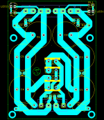
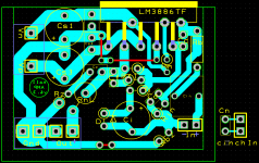
New v6.3 AMP with bigger drill holes, and a jumper to allow separation of power, speaker, and low-level return.
New v2.3 PSU with added LEDs.
What I'd like to include would be fuses to prevent accidents. First a fuse before the toroid, and then a second pair, but where would be better (or even necessary?) between PSU and toroid or between PSU and AMP? (my guess would be the latter.)
cheers!
hurtz
New v2.3 PSU with added LEDs.
What I'd like to include would be fuses to prevent accidents. First a fuse before the toroid, and then a second pair, but where would be better (or even necessary?) between PSU and toroid or between PSU and AMP? (my guess would be the latter.)
cheers!
hurtz
Attachments
There must be a fuse in the primary circuit. It is normally placed as the FIRST item as the mains enters the chassis..............What I'd like to include would be fuses to prevent accidents. First a fuse before the toroid, and then a second pair, but where would be better (or even necessary?) between PSU and toroid or between PSU and AMP? (my guess would be the latter.)
Secondary fusing is usually placed after the main smoothing bank of capacitors. Placing the secondary fusing before the smoothing requires the fuse rating to be so high that it is virtually useless in limiting damage in event of a serious fault condition.
BTW,
fusing does not prevent accidents. Fusing is intended to prevent your house burning down after the accident.
fusing does not prevent accidents. Fusing is intended to prevent your house burning down after the accident.
Yep. That's when the smoke that runs the electronics escapes and they stop working.
AndrewT said:There must be a fuse in the primary circuit. It is normally placed as the FIRST item as the mains enters the chassis.
It is included in the socket.
I would calculate the primary fuse like this:
Code:
80VA = 230V * xA
I = 0.35A
Next bigger Fuse: 0.4A
Now there are three types, fast, medium, and slow. I know fast won't work because of the inrush current. But I have no idea whether medium or slow is the right choice.
AndrewT said:Secondary fusing is usually placed after the main smoothing bank of capacitors. Placing the secondary fusing before the smoothing requires the fuse rating to be so high that it is virtually useless in limiting damage in event of a serious fault condition.
I see. How do I get information on the current limits for the secondary fuses? A look at the datasheet (page 9 top left graph) tells me that the curent within the safe-zone can be virtually anything as long as the pulse is short enough.
AndrewT said:BTW,
fusing does not prevent accidents. Fusing is intended to prevent your house burning down after the accident.
Would be an accident for me
")
mwmkravchenko said:Yep. That's when the smoke that runs the electronics escapes and they stop working.
Sometimes you can even hear the "pop" when the sound gets out as well!
cheers!
hurtz
P.s. will comment on the multi-channel setup later!
Sometimes you can even hear the "pop" when the sound gets out as well!
I forgot about that one.
My best pop story is setting up a supply board at 3:00 AM. Plugging it directly into the mains socket and hearing a strange high pitch sound. And then boom, like a shot gun. All the caps blew their tops off. I had soldered them in backwards!
So yes there can be noise in them there cans!
The transformer can supply low current when the demand is low.
It can supply high current when the demand is high.
It can also survive massive overloading without any damage if the transient duration is short enough.
All these different loading situations can be imposed by a correctly operating amplifier.
I find the best way to determine the lowest fuse to provide that house burning down protection for the secondary side is to use the amplifier rating as a guide to the fuse size.
My rule and Quasi's rule are almost identical.
Amplifier maximum output power leads to maximum output current into your nominal load.
eg.
100W into 8ohms speaker is equivalent to 40Vpk and 5Apk into a nominal 8r0 load.
The secondary fuse in each supply rail should be ~ half that value i.e. F2.5A.
Quasi uses rms output current as the guide.
The same 100W into 8ohms amplifier has 28.2Vac and 3.5Aac. He suggests a secondary fuse for each supply rail of ~F1.75A, i.e use F2A
Both these rules have been stated in many previous posts.
From post #195:
@Mike
Please take a look at post #159, the PSU doesn't have a common 0V point, so the "master" 0V is on the AMP board, no point in shifting it to the PSU.
Mike
Forgive me, I see your point now.
eg.
100W into 8ohms speaker is equivalent to 40Vpk and 5Apk into a nominal 8r0 load.
Hmm don't you mean 200W?
Code:
U * I = P
40 * 5 = 200
So the here my calculation:
(18V secondaries)
18 * 1.41 = 25.5V
(And not 51V because 25.5V is the maximum voltage difference one can reach from 0V)
Into 8r0 load: 3.2A
But! Isn't this the maximum current one rail can draw at a time? That is one 3.2A fuse per rail?
---
Multi channel setup:
I would set the Front-left as master 0V and then return all the other 0V lines to this one, i.e. speaker return, low-level, and RCA. On the other AMP boards the power-0V will of course also be returned to the front-left.
cheers!
hurtz
Power = voltage times current.
That rule applies to constant DC supplies and constant DC current to the load.
If the supply varies or the load current varies then the rule becomes:
Power = root mean squared of voltage times root mean squared of current, normally written as P = Vrms * Irms
If you have peak current of a sinusoid waveform and peak voltage of that same sinusoid then the rule must be reworded to convert the peak current and peak voltage of the sinusoid back to root mean squared to give the same heating effect as the original rule.
If using peak values of sinusoid waveform then the rule becomes:
Power = Peak voltage times peak current divided by 2, i.e.
P = Vpk * Ipk / 2
Remember this all goes back to equivalency to the heating effect of constant currents through constant loads, i.e. constant DC operation.
the current in the power rail flows for half the time. The heating effect is halved. The fuse rating is halved accordingly. Otherwise the fuse wire will not heat up enough to melt and rupture.The secondary fuse in each supply rail should be ~ half that value
F1.6A, F2A or F2.5A and F3.15A are the available fuse values.
But, you have it wrong.
68W into 8r0 is ~33Vpk and ~4Apk. giving an F2A fuse for 8ohms speaker.
68W into 6r0 is ~28.6Vpk and ~4.7Apk. Giving an F2.5A fuse for 6ohms speaker.
68W into 4r0 is ~23.3Vpk and ~5.8Apk, Giving an F3.15A fuse for 4ohms speaker.
Note that the 4ohms to 8ohms current ratio is sqrt(2), not 2.
Quasi's version of the rule reduces all the fuse values by sqrt(2). This takes account of the rms value of a sinewave rather than the peak value that I use.
But my peak Voltage is always the same! I get your calculation using 68W und then multiplying by sqrt(2) to get the peak values. What I don't get is why I should assume P and R as fixed values to calculate I, rather than R and U.
Since my guess would be that for short pulses "Spike" doesn't kick in and the maximum 68W rating doesn't apply!
cheers!
hurtz
Since my guess would be that for short pulses "Spike" doesn't kick in and the maximum 68W rating doesn't apply!
cheers!
hurtz
Last edited:
- Status
- This old topic is closed. If you want to reopen this topic, contact a moderator using the "Report Post" button.
- Home
- Amplifiers
- Chip Amps
- The yet tiniest single-sided LM3886?