I'm using coaxial for my chipamp, core to screen capacitance is >90pF.
Do I still need to add RF attenuation across the RCA?
Average gain of my amp around 20dB and input coupling F -3dB @ 1.5Hz.
therefore
F -2dB @ 3Hz
F -1dB @ 6Hz correct?
so after the 20dB gain, is 6Hz -20dB lower than higher Hz?
and 1.5Hz -60dB?
What are the function of diodes after volume POT?
I found sort of this layout from google.
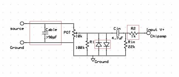
What can I do to the input? in order to force the non-inverting input to see only 1kOhm from ground, no matter what position of POT at.
Do I still need to add RF attenuation across the RCA?
Average gain of my amp around 20dB and input coupling F -3dB @ 1.5Hz.
therefore
F -2dB @ 3Hz
F -1dB @ 6Hz correct?
so after the 20dB gain, is 6Hz -20dB lower than higher Hz?
and 1.5Hz -60dB?
What are the function of diodes after volume POT?
I found sort of this layout from google.
What can I do to the input? in order to force the non-inverting input to see only 1kOhm from ground, no matter what position of POT at.
Last edited:
")
The input of any audio equipment must allow the AUDIO SIGNAL to pass.
It would be preferable that the components that are used in the inputs would stop/block all non-Audio Signals.
That cannot be achieved in practice. It is impossible to block all the interference and yet pass all the audio.
We settle for using low pass and high pass filters that let the vast majority of audio signal to pass and attenuate some or all of the non audio interference that comes in via any of the inputs.
You select these filter characteristics to suit your equipment and your environment and your ears.
The low pass filter must be designed to pass all the treble and all the middle Audio signal.
It must also pass a proportion of the bass signal. You have to choose where to put that filter turn over frequency and what rate of attenuation you use out of passband.
Similarly, the high pass filter must be designed to pass the majority of the audio signal and yet be capable of attenuating as much of the non-audio signal as possible. Again you do this by choosing the turnover frequency and the rate of attenuation out of pass band.
Do you need more?
Hint:
find your high pass and low pass filters and calculate your pass band F-3dB frequencies and find the rate of attenuation out of passband.
Last edited:
that's the formula that predicts the F-3dB turnover frequency for a single pole RC filter.
The High Pass is the 22k and the 4u7F giving a RC time constant of 103milliseconds (103ms) & F-3dB ~1.6Hz and F-1dB ~ 3Hz. This is very typical of the High Pass fitted to commercial "HiFi" power amplifiers.
Some builders choose a little lower, some go to Servo & DC coupled to go a lot lower and some go much higher. I happen to prefer around this value and generally aim for ~90ms.
I cannot identify your Low Pass filter.
It depends totally on which interconnect you choose, both Length and type and on the source equipment you choose.
The Power has no control whatsoever on what interference is allowed to enter.
I consider this arrangement to be non-design, rather worse than bad design. To me totally unacceptable. The Google circuit is the equivalent to sticking a damp finger in the air and using the information gathered, to say that plane up there is flying to Timbuktoo !
Last edited:
- Status
- This old topic is closed. If you want to reopen this topic, contact a moderator using the "Report Post" button.
- Home
- Amplifiers
- Chip Amps
- Input of Chipamp