Hi,
Maybe you can help me with your suggestions and adjetives to my head. I think that given the money the GC requires, I have a magnifique oportunity to biamp.
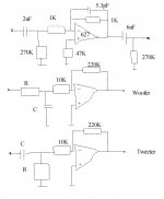
What do you think of the scheme? I don't mean the graphics quality (isn't it the lovely? ), but the scheme concept.
My concern is if I got the filters right. I put the lpf at 33Khz in the very buffer and then I follow with the hipass and lowpass. This way the woofer is lowpassed twice, but I don't know how to do this only once.
Yeah, I know that both drivers should have same sensivity, actually the drivers I'm thinking of are both 90dB. I'm thinking about providing some filter adjustement but maybe I keep it simple by now.
Any support is appreciated.
Maybe you can help me with your suggestions and adjetives to my head. I think that given the money the GC requires, I have a magnifique oportunity to biamp.
What do you think of the scheme? I don't mean the graphics quality (isn't it the lovely?
), but the scheme concept.My concern is if I got the filters right. I put the lpf at 33Khz in the very buffer and then I follow with the hipass and lowpass. This way the woofer is lowpassed twice, but I don't know how to do this only once.
Yeah, I know that both drivers should have same sensivity, actually the drivers I'm thinking of are both 90dB. I'm thinking about providing some filter adjustement but maybe I keep it simple by now.
Any support is appreciated.
Attachments
Hi Raka
I understand that you want to cross over with 6dB/octave, right ?
IMO it doesn't matter for the woofer to be lowpassed twice since the input filter's pole is way above any usual crossover frequency.
But if you really want to use a 1st order only crossover, why not do it simple ?
Your circuit will of course work well but there would be an even simpler solution:
Make the lowpass for the woofer via a capacitor in the feedback path of the GC, like you do it as input filter.
The highpass can be built by the C and the 10 k input resistor only (i.e. leave the resistor to ground).
Since there are stability issues with these integrated amplifiers this has to be tried out in practice first of course.
Regards
Charles
1st order, of course
Yes, I intend to use 1st order, the woofer is a 6,5" and the tweeter is a 1" fs=850Hz, so the only thing to decide is the crossover point. I'm thinking about the simplest way to change the RC net without using the soldering (once finished) but as the behaviour of the drivers is exemplary, I think I can't go wrong crossing not high and not low.
Thanks for your suggestion about simplifying the implementation. If I get out the R in the tweeter section I get the C value by
C=1/2*PI*10K*Freq, right?
Hi Raka
This is correct. You might however use your proposed circuit to conveniently determine the x-over frequency.
You will have to watch out for DC at the tweeter amp's output, maybe even use a DC-blocking cap for the tweeter (I know this is not ideal but a blown tweeter might be even less ideal).
Regards
Charles
C=1/2*PI*10K*Freq, right?
This is correct. You might however use your proposed circuit to conveniently determine the x-over frequency.
You will have to watch out for DC at the tweeter amp's output, maybe even use a DC-blocking cap for the tweeter (I know this is not ideal but a blown tweeter might be even less ideal).
Regards
Charles
About the tweeter helping, I know that the buffered clone has some turn on-off nasties due to the additional power supply, so I will provide standby power to all the stages but to the LM3875, and the ON-OFF button will exclusively operate the LM power supply.
BTW, the panasonic FC doesn't have the ghost effect it scaried me a lot with my budget caps GC
BTW, the panasonic FC doesn't have the ghost effect it scaried me a lot with my budget caps GC
Thinking....
"When filtering slew induced problems, only by going the passive route can you be completely sure. I learnt this by rebuilding IV and Buffer stages in CD Players over many years. Whenever you went passive the sound improved in fundamental ways."
Extracted from Pedja's site, said by Rasmussen.
So, wouldn't it better to filter passively, than with the cap in the feedback path?
Charles,
Thanks for your reply. I'll try first the passive way and see what happens.
I've been thinking (no jokes here) and have some doubts:
the 6uF and 270 resistor could be ommited, right? The tweeter has a high pass filter, so why put a cap before? The woofer input should be AC coupled? It doesn't suffice the input 2uF and 270K resistor? Would the DC offset at the woofer output a problem? If the 627 has a 5mV offset, the gain of the LM would convert to a 5mVx23=115mV, not including the offset of the LM itself, am I right? Should I translate the cap to the woofer stage before the low pass RC? When I'll stop making questions?
Hi Raka
That's right !
Some GC guys seem to have offset adjustment implemented with great success. So the large C might be completely omitted if done properly.
Regards
Charles
the 6uF and 270 resistor could be ommited, right? The tweeter has a high pass filter, so why put a cap before?
That's right !
Some GC guys seem to have offset adjustment implemented with great success. So the large C might be completely omitted if done properly.
Regards
Charles
Thanks, I've just saved the money for the 6uF cap  !!
!!
The 270K resistor is not needed so another cent. for the pig
Well, the offset can be controlled by a pot in the + leg of the LM to equal impedances seen from both legs, so I suppose I can manage to solve the offset of the LM, but can be done the same way with the OPA627?
To get more flexibility, I think I'll also provide different caps and resistors in the RC net, to allow changes in the crossover points for fine tunning.
!!The 270K resistor is not needed so another cent. for the pig
Well, the offset can be controlled by a pot in the + leg of the LM to equal impedances seen from both legs, so I suppose I can manage to solve the offset of the LM, but can be done the same way with the OPA627?
To get more flexibility, I think I'll also provide different caps and resistors in the RC net, to allow changes in the crossover points for fine tunning.
Sonic character
Just to inform about the progress:
I'm designing a PCB+P2P layout, incorporating a connector for switching the passive net before the LM. It's going well, not fast because of the beach, but I've found out that the sensivity of the tweeter I had in mind is not the same as the woofer, but 2÷3 dB higher.
I'm thinking to change the gain of the GC to compensate, but I'd like to hear some comments about the sonic change that could bring out this. Would be better to have less feedback on the tweet or on the woofer?
Re: 1st order, of course
Now that you are getting ready to build your circuit, perhaps you should consider a second order passive input filter. The only problem with such filter is that it will drain some of your preamp signal, but if you have a preamp you can increase the gain to compensate.
You certainly should use a film capacitor at the power amp driving the tweeter for protection.
Carlos
Raka said:Yes, I intend to use 1st order, the woofer is a 6,5" and the tweeter is a 1" fs=850Hz, so the only thing to decide is the crossover point. I'm thinking about the simplest way to change the RC net without using the soldering (once finished) but as the behaviour of the drivers is exemplary, I think I can't go wrong crossing not high and not low.
Thanks for your suggestion about simplifying the implementation. If I get out the R in the tweeter section I get the C value by
C=1/2*PI*10K*Freq, right?
Now that you are getting ready to build your circuit, perhaps you should consider a second order passive input filter. The only problem with such filter is that it will drain some of your preamp signal, but if you have a preamp you can increase the gain to compensate.
You certainly should use a film capacitor at the power amp driving the tweeter for protection.
Carlos
- Status
- This old topic is closed. If you want to reopen this topic, contact a moderator using the "Report Post" button.
- Home
- Amplifiers
- Chip Amps
- Biamping for tontos