Hi Guys,
I'm in the middle of a chipamp.com 3886 build, so far the PSU functions well, but when I put power to the assembled amp boards something shorts out. The amp boards are pretty simple and I've triple checked it for possible solder bridges, and miss-installed components. I checked the amp board power traces with my DMM and could find no obvious problems/shorts. Everything looks fine and no smoke or anyother sign of a problem with the amp boards or components is evident. I even removed one of the amp chips and found that the board was still drawing a pretty heft load even though it didn't blow the fuse. Has anyone had an experience with bad amp boards causing symptoms like this. Does anyone have any advice on other diagnostics that I might try.
Thanks,
PJN
Hi Guys,
I've built several successful projects before without problems, a couple of RevC's, a descrete amp, a couple of preamps and two DAC's so my soldering skills aren't terrible. I'll post a couple of pics. The PSU puts out a steady +/- 34vdc at no load, I'll try measuring it with a load.
Thanks,
PJN
I've built several successful projects before without problems, a couple of RevC's, a descrete amp, a couple of preamps and two DAC's so my soldering skills aren't terrible. I'll post a couple of pics. The PSU puts out a steady +/- 34vdc at no load, I'll try measuring it with a load.
Thanks,
PJN
Hi Guys,
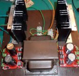
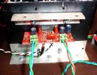
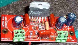
Here are a few pics of the test rig and boards. I put things together with stuff that I had lying around in my parts bin, but all parts values matched the BOM. I did use mica insulators between the chip and the heat sink and the spreader bar and the chip, and the heat sinks are mounted on a board.
PJN
Attachments
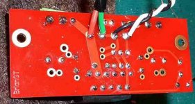
that bracket that bolts the chip to the heatsink is it plastic or metal and is it isolated from the chip as well? With the powersupply unpluged and everything put together ohm out the +/- rails to ground, you should see 0 ohms and the caps slowly charging from the ohm meter. check for any electrolytic installed backwards
Sregor,
That makes sense, I am using an old transformer and it is center tapped. It has only one ground and two leads. On my other builds I have always used torroids, with two separate grounds and leads, so I am unfamiliar how to wire up a CT trafo. All I did was to run the ground to both PSU boards. Can you provide some guidance as to how to properly hook up a CT trafo.
Thanks,
PJN
You can use a ct trafo with ChipAmp.com's PSU board, even though it wants two separate secondary windings. You'd have to connect the center tab to the ground and then to use only half of each of the two bridges by connecting one AC lead to one (the correct one) of the two AC inputs on either side of the board.
more info at: http://www.diyaudio.com/forums/chipamp/179151-using-snubberized-psu-board-ct-trafos.html
Pictures of the chip amp boards with CT on this page courtesy apex jr (no association) miscellaneous.html
There are other discussions - probably should be a sticky.
Pictures of the chip amp boards with CT on this page courtesy apex jr (no association) miscellaneous.html
There are other discussions - probably should be a sticky.
I got everything straightened out according to the info that you guy pointed me to on the CT trafo power supply and everything is up and running sucessfully. The DC offset on the two amps was -45 mv, and -48 mv, and installing Ci didn't make a difference so I left it out. I gave it a quick listen on some cheap junk speakers and it sounded clear without any hiss or hum. Now I need to throw every thing into a proper case and give it a serious listen. Thanks a lot for your help.
PJN
PJN
- Status
- This old topic is closed. If you want to reopen this topic, contact a moderator using the "Report Post" button.
- Home
- Amplifiers
- Chip Amps
- A strange problem with new chipamp build