Hi!
I want to connect my MP3 player to my Car Audio AUX input, but the signal is a little bit weak, so I would like to amplify it by a factor of 2-6.
I think an NE5532 opamp would have enough good quality for this purpose (Do you agree? ). I don't need bass, treble or balance control (can be controlled already on both the MP3 and the car audio), just gain/volume control (some MP3 players are louder and doesn't need so much pre-amplification).
My questions:
- Should I use a dual power supply or a single with virtual ground?
- Would a simple non-inverting amplifier (like on the picture) be enough good? (with capacitors on input and output )

- Replacing R1 and R2 with a linear potentiometer for gain/volume control would be a good idea?
- Could you post me a simple schematic or a link?
- I already looked at a design ( Simple High Quality Preamp For Hi-Fi ) but I do not have much experience with analog circuits. Which parts of the circuit should be kept if I only need simple amplification with gain control?
Thanks in advance!
Aaron Szabados
I want to connect my MP3 player to my Car Audio AUX input, but the signal is a little bit weak, so I would like to amplify it by a factor of 2-6.
I think an NE5532 opamp would have enough good quality for this purpose (Do you agree? ). I don't need bass, treble or balance control (can be controlled already on both the MP3 and the car audio), just gain/volume control (some MP3 players are louder and doesn't need so much pre-amplification).
My questions:
- Should I use a dual power supply or a single with virtual ground?
- Would a simple non-inverting amplifier (like on the picture) be enough good? (with capacitors on input and output )
- Replacing R1 and R2 with a linear potentiometer for gain/volume control would be a good idea?
- Could you post me a simple schematic or a link?
- I already looked at a design ( Simple High Quality Preamp For Hi-Fi ) but I do not have much experience with analog circuits. Which parts of the circuit should be kept if I only need simple amplification with gain control?
Thanks in advance!
Aaron Szabados
that is intresting, it should not be weak actualy, headphone output should drive it properly.
But anyways, single supply would be okay, or You can use a simple resistive divider to get dual supply. Makes no difference if You ask me (in this application at least).
If You ask me, the simples solution would be a set gain somewhere around a factor of 3, and add a simple potmeter to the input of the opamp. So the gain is fixed, You just trim the input with the pot till it is suitable for Your amplifier.
MP3 players seem to have notoriously weak output. Your non-inverting op amp is probably the easiest solution. Do you really need variable gain, or a volume control? Volume can be controlled via the head unit. What I would suggest is to set the volume on the MP3 player where you want it, then determine the amount of gain needed to give an adequate signal to the aux input. You can do this by measuring the signal amplitude and comparing it to the head unit's input sensitivity or you can "play it by ear." 2x to 6x ought to be in the right neighborhood. Set the op amp for that fixed gain.
A single-supply virtual ground is what I would use, with a capacitor on the op amp output. A capacitor isn't needed on the input as the MP3 player likely has one on its output anyway.
I'd be wary of using a shared ground with the rest of the system. For me, these are the sort of things that cause me ugly ground loop issues. I'm thinking I'd use a separate small 12VDC SLA battery, using it create a virtual ground +-6V supply for the op amp and regulating it down to power the MP3 player . An accessory (cigarette lighter) plug could be added to recharge the battery via a dashboard socket.
I don't want to use a separate battery, it should be powered from the car's +12V rail. The reason is, that this preamp will be part of a "factory CD-changer faker". My Volkswagen Beta radio has a CD-changer input (it has no real general purpose AUX), which can only be enabled by a factory CD-changer head unit. My circuit fakes this head unit, and I want to add audio signal amplification to it.
The cars supply is quiet noisy, but I think it could be "cleaned up". I think the +12V is also full of spikes. My car has Start-Stop system, so the engine is stopped every time you stop and it starts automatic as soon as you accelerate,. I think this will also affect the stability of the +12V supply.
What about using a 7809 voltage regulator? Wouldn't it be enough to get a stable supply for my preamp? Or maybe some sort of DC-DC converter? And of course bypass and filter caps.
"I want to connect my MP3 player to my Car Audio AUX input" is what you said in your original post, so I went with that. If this is only part of a larger circuit that's fine; adjust accordingly.
I assume GND is part of the CD changer interface. Maybe that's a good ground point for the additional circuit. But it is a "faker" after all, so separate battery power isn't necessarily excluded. Electric and hybrid vehicles are beyond my experience though.
A 7809 should work, but a LDO regulator may be a better choice here.
#1: I don't want to save myself from building this, I am a Computer Engineer student, I have some basic experience with developing embedded systems (digital circuits) and I would like to extend my knowledge with some analog circuits ")
#2: My head unit doesn't have a real AUX input, it's input is intended only for the factory CD-changer unit, so it doesn't have a gain control. This is actually a radio hack.
#3: Look at the attached file, this is what I came up with. It could be the worst preamp you have seen in your life, hope you can help making it better. I have not drawn the power supply yet. My idea is to use a buck/boost (SEPIC) converter to create a +10V rail from the +12V of the car (which variates between 9-14V) , and to use another buck converter to create a +5V rail for the virtual ground, uC and digital circuits.
#2: My head unit doesn't have a real AUX input, it's input is intended only for the factory CD-changer unit, so it doesn't have a gain control. This is actually a radio hack.
#3: Look at the attached file, this is what I came up with. It could be the worst preamp you have seen in your life, hope you can help making it better.
I have not drawn the power supply yet. My idea is to use a buck/boost (SEPIC) converter to create a +10V rail from the +12V of the car (which variates between 9-14V) , and to use another buck converter to create a +5V rail for the virtual ground, uC and digital circuits.Attachments
Datasheet minimum supply voltage for the 5532 is +/-5V.
I would not use it in a circuit that has +4,-5V supplies. Note the output will also be limited to some value much lower than the supply voltage.
You could use an ~8V LM317 based regulator and the ever popular OPA132 series opamp, good for supplies down to +/- 2.5 V. Use a virtual ground on this: Two 5-10k resistors each with 220uf across them.
Put an RC filter before the regulator (~10 Ohm, 1000 uF).
Use R2 = 10k, R1 = 3.3k, nice 4x gain.
Use R3=100k for lower noise. Get rid of R4, C2. Use virtual ground.
Remove R5 or R8.
Add a 220pf cap across R3 for HF suppression. Make R6 3.9k (also move R6 before R3).
Datasheet minimum supply voltage for the 5532 is +/-5V.
I would not use it in a circuit that has +4,-5V supplies. Note the output will also be limited to some value much lower than the supply voltage.
You could use an ~8V LM317 based regulator and the ever popular OPA132 series opamp, good for supplies down to +/- 2.5 V. Use a virtual ground on this: Two 5-10k resistors each with 220uf across them.
Put an RC filter before the regulator (~10 Ohm, 1000 uF).
Use R2 = 10k, R1 = 3.3k, nice 4x gain.
Use R3=100k for lower noise. Get rid of R4, C2. Use virtual ground.
Remove R5 or R8.
Add a 220pf cap across R3 for HF suppression. Make R6 3.9k (also move R6 before R3).
I tried your suggestion but the simulation results make me worry What's wrong? (Check attachement!)
Why do you think, that using a virtual ground is better than pulling the input signal to VCC/2 ? I have never designed any audio amplifiers, but this worked pretty well in my ultrasonic rangefinder design
Attachments
Remove C1, it is too small for the lower feedback circuit.. You do not need it with a virtual ground...
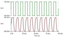
It is much better now (attachment!), but I still see some distortion in the resulting square wave.
The Bode plot looks also much better. What do you think about the phase shift, is it acceptable?
So tell me what are the draw backs of just pulling the input to VCC/2 instead of using a virtual ground?
Attachments
Nothing wrong with the square wave.
C3-R3 and C4-R7 blocks DC and this is the result with a 100Hz square wave.
You have a freq. response around 5Hz to 100 kHz (-1dB).
You can modify this by playing with C2, C3 and C4, but the values you have now are right in the ball-park.
Test square waves 1k, 10k and 100k.
If there is no or little overshoot and nice fast rise/fall times, you are good.
Change the scales on the gain/phase curves to see something more meaningful, -20dB to +20dB, +20 to - 180 degrees, 1Hz to 1MHz.
The virtual ground is just a simple way to get Vcc/2.
Your bigger problem might be ground loops in the final installation....
Nothing wrong with the square wave.
C3-R3 and C4-R7 blocks DC and this is the result with a 100Hz square wave.
You have a freq. response around 5Hz to 100 kHz (-1dB).
You can modify this by playing with C2, C3 and C4, but the values you have now are right in the ball-park.
Test square waves 1k, 10k and 100k.
If there is no or little overshoot and nice fast rise/fall times, you are good.
Change the scales on the gain/phase curves to see something more meaningful, -20dB to +20dB, +20 to - 180 degrees, 1Hz to 1MHz.
The virtual ground is just a simple way to get Vcc/2.
Your bigger problem might be ground loops in the final installation....
Ok here are some more test, with different frequency square wave. What do you think, will it sound good?
Frequencys from the left to the right: 100k ;30k; 10k; 20Hz; 1k
Attachments
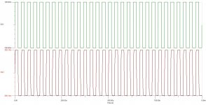
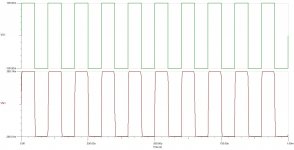
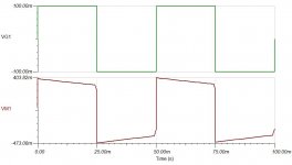
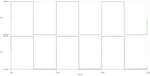
There is some random clipping on the trailing corners that you did not have before?
But the basic circuit you had in post 13 will be fine, it is textbook.
Simulator cannot tell you much more on a simple circuit like this - the variables will be in power supply, part selection, PCB layout and interconnection...
Do not forget to put ~100nF very close to each supply pin of the chip.
Use MKT for C3 and C4 (MKP if you must, but this is car audio). MKP, silver mica, C0G or X7R for C2.
This is what I wanted to ask next
I am very space constrainted, I want to use X7R 0805 SMD ceramic capacitors and standard 5% tolerance 0805 SMD resistors, and NE5532D (SOIC package). Are these parts OK for this circuit, should?
I know there is no 220uF 0805 SMD ceramic cap but I think using a some IC for the cirtual ground would be better than a voltage divider? For example a two DC/DC converters? One for VCC and one for VCC/2.
My idea for the power supply:
12V Car battery -> 78L09 for +9V -> TC7660 for -9V
This is a cheap solution, I am not interested in efficiency, power drawn by the circuit won't be more than 50mA I think. (actually it should be much less?)
I get a regulated +9V with the 78L09 and than I invert it with the TC7660 charge-pump, which will give me at least -8V under load. So instead of using a VGND I will use a real negative supply.
Switching frequency of the TC7660 is 35kHz, I think this won't affect the audio signals.
Do you think this is a good solution for the power supply?
I would use at least wima mkt2 for the 2.2 uF caps.
You should put at least a few hundred uF on the power supply input side.
For the resistors, try at least to have metal film type. However, for MP3 player to car audio, maybe this does not make a big difference.
DC-DC switchers will need to be done very well not to impede the performance of the circuit. If you will hear the difference, that is debatable. If you do go that way, rather generate -15V from +battery and then (linear) regulate that to -9V?
Use LM317/337, with bypass capacitor on the Vadj pin, rather than the 78/79 series - lower noise.
I would still use an OPA132 or maybe an AD823 with a simple 317 8V regulator (or 10V LDO reg) and virtual ground. You can try the popular TLE2426 for virtual ground.
PS: Note that you are simulating using a FET input opamp and want to use a BJT input opamp. They are not the same beasts.
- Status
- This old topic is closed. If you want to reopen this topic, contact a moderator using the "Report Post" button.
- Home
- Amplifiers
- Chip Amps
- Preamplifier with NE5532 for CAR Audio