Got 2 pairs of TDA7294 bridged with single reticifier bridge and 10000uF on + & - rails in the same pcb (all, two 10000uF caps, four TDA chips etc on the same PCB - so I can only feed all theese four chips from one PSU). Sounded ok, but got also transformer hum audible trough speakers. Transformer is torodial 600VA 2x24V secondaries. Then I removed existing bridge and wired up external recitifer with two diode bridges. Sound changed to muddy trebles and mids, but transformer hum weren't there any more. This got me tottally confused...
I'm a noobie to electronics, so I ask you for dumbed down") version for good TDA7294 bridge power supply. How mutch what, why and where etc... Thank you in advance.
version for good TDA7294 bridge power supply. How mutch what, why and where etc... Thank you in advance.
I'm a noobie to electronics, so I ask you for dumbed down
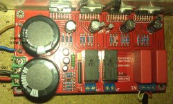
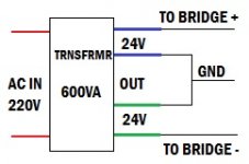
version for good TDA7294 bridge power supply. How mutch what, why and where etc... Thank you in advance.As you can now see (check atachments), original power supply for theese 4 TDA's exist from 25A bridge (not seen, but you can see where it was) and 2 10000uF caps. I have a 600VA 2x24V transformer, so I connected transformer as seen in diagram (see atachments). As I searched trough varios posts here, I made a conclusion, that this crappy PSU may be the reason why I could hear transformer hum from speakers.
Also I tried 2 brige config with more caps between transformer and pcb, but sound was muddy and terrible in result (that is why you can't see in pictures original bridge but see soldered vires instead, AC vire is there to supply with power speaker protection ciricuit, that has it's own one diode reticifier).
Also I tried 2 brige config with more caps between transformer and pcb, but sound was muddy and terrible in result (that is why you can't see in pictures original bridge but see soldered vires instead, AC vire is there to supply with power speaker protection ciricuit, that has it's own one diode reticifier).
Attachments
something to try:
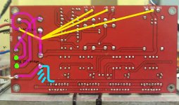
In the image below, the purple tracks or areas show where the 50/60 Hz ripple currents are. These tracks will radiate mains noise and need to be as short as possible and run in tights pairs with the corresponding current return track.
Blue shows how the power should have been taken from the filter capacitor. Possibly similar issue on other side.
The board uses a ground plane, but segregated to form a kind of star ground. The signal ground should also be on this star, not on the leg of one filter capacitor as it is at the moment.
So many things not ideal and possibly a few errors that should be fixed. But to answer your current question, you can try to put the original bridge back and solder the transformer wires directly onto the green dots. Bring all four wires to the board, tightly twisted together, and put the 2 grounds on the original ground screw terminal.
PS. No sign of a Zobel network? What is the red wire (hope it is not the 4th transformer wire)?
EDIT: Bridged amplifier, so please ignore the corresponding yellow lines from the outputs back to the star ground shown on the image.
Attachments
Last edited:
Yesterday soldered and wired all back as originally was (reading your replies only now). As It turns out, the messed up thing was the speaker I used for testing - somehow it lost its tweeter (will open up speaker and check why today, it's a 8ohm PA speaker with 800W max rating), so only lows and mids were audible, so all my testing with different configurations was pointless (tried to add more caps between bridge and chip, got 4x 6800 uF 80V laying around).
So... What can and should I do to get rid of transformer noise?... I'll try to record sample of it today and post here.
Sorry, but what is a Zobel network?PS. No sign of a Zobel network?
The red wire is AC only to supply the onboard speaker protection circuit, wich has its own one diode recitifer.What is the red wire (hope it is not the 4th transformer wire)?
So... What can and should I do to get rid of transformer noise?... I'll try to record sample of it today and post here.
Try this as a first step:
The idea is to minimize the length of tracks that carry 50 Hz current pulses. (Between the transformer and the big filter capacitors).
Make sure to keep the transformer wires away from the circuit board, the speaker wires and the input wires. Speaker wires and input wires should also be twisted together (each input with its own ground wire up to the circuit board).
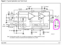
The zobel network is a kind of snubber to suppress high frequency oscillation and noise pickup on the output terminals. It is shown on the 7294 datasheet for a standard amplifier (ST calls it a boucherot cell). ST does not show it for the bridged circuit on the same datasheet, and mentions it is optional for the standard circuit, so you may be ok without it. Without an oscilloscope, you may never know though.
But to answer your current question, you can try to put the original bridge back and solder the transformer wires directly onto the green dots. Bring all four wires to the board, tightly twisted together, and put the 2 grounds on the original ground screw terminal.
The idea is to minimize the length of tracks that carry 50 Hz current pulses. (Between the transformer and the big filter capacitors).
Make sure to keep the transformer wires away from the circuit board, the speaker wires and the input wires. Speaker wires and input wires should also be twisted together (each input with its own ground wire up to the circuit board).
The zobel network is a kind of snubber to suppress high frequency oscillation and noise pickup on the output terminals. It is shown on the 7294 datasheet for a standard amplifier (ST calls it a boucherot cell). ST does not show it for the bridged circuit on the same datasheet, and mentions it is optional for the standard circuit, so you may be ok without it. Without an oscilloscope, you may never know though.
Attachments
That sounds like more than just noise pickup/bad layout. Did you short out the two inputs to ground when you recorded the sound?
I would guess either or both of the filter capacitors are bad (under rated Chinese knock-offs?)
Or, less likely, a bad bridge.
Are you 100% sure about the transformer wiring? You show 2 greens as one coil and 2 blues as another on your diagram above. If it is an Antek transformer, this is wrong....
I would guess either or both of the filter capacitors are bad (under rated Chinese knock-offs?)
Or, less likely, a bad bridge.
Are you 100% sure about the transformer wiring? You show 2 greens as one coil and 2 blues as another on your diagram above. If it is an Antek transformer, this is wrong....
Input was connected to Behringer Eurorack mixer with all pots down to -∞ (e.g. no sound) when I did the recording. The sound doesn't change much when I leave input not connected.
I tried changing only bridge in original place - same results.
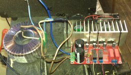
It's polish INDEL transformer 600VA, 50Hz, prim 220V, sec 2x24V 2x12.5A. Here's a little messy picture of all wired up in original config. (updated picture with vire explanation, ignore vire colors)
I tried changing only bridge in original place - same results.
It's polish INDEL transformer 600VA, 50Hz, prim 220V, sec 2x24V 2x12.5A. Here's a little messy picture of all wired up in original config. (updated picture with vire explanation, ignore vire colors)
Attachments
Last edited:
The transformer wiring seems OK from the picture, but I did not find a schematic for that transformer to be 100% sure.
I would still replace those two filter capacitors to eliminate them as suspects. 1000 to 2200 uF is good enough for testing purposes. Be careful not to damage the circuit board. (If you had access to an oscilloscope you could test in circuit, without replacement)
Do you have a multimeter? Now would be a good time to invest in a cheap one.
You need to measure (with audio inputs still at zero):
1. AC voltage between each phase and GND from the transformer. Should be around 24-26 VAC
2. AC voltage between the two phases from the transformer. Should be double what you have in item 1 above
3. DC voltage across each of the two big filter capacitors. Should be around 33-36 VDC.
4. DC voltage (milli-volts) across each speaker output. Should be less than 50 mVDC.
Do not connect speakers yet, or use a cheap one wired in series with something like a 10W 220 ohm resistor for testing purposes.
Also read up on the light-bulb tester. Use a 20-40W lamp. Could save your equipmentif something goes wrong. Use a 1A slow blow fuse in the primary of the transformer until you find the problem.
Shorted inputs first. Connected 10W 4ohm test speaker in output. Replaced 10000uF caps with two new 2200uF, that damn noise still there.
Don't have scope, wish I had, seems very usefull and interesting tool, but I have a cheapy multimeter. Mesured what you asked.
Any ideas? Seems to me that I shoud throw that chineese crap in trash, find here a scheamtic & start over...
Don't have scope, wish I had, seems very usefull and interesting tool, but I have a cheapy multimeter. Mesured what you asked.
23,8V AC both1. AC voltage between each phase and GND from the transformer. Should be around 24-26 VAC
48,2 AC2. AC voltage between the two phases from the transformer. Should be double what you have in item 1 above
+32,7 & -32,7 V DC3. DC voltage across each of the two big filter capacitors. Should be around 33-36 VDC.
Got interesting results, one was 6,7 and other was -15,9 (multimeter set to 200m DC)4. DC voltage (milli-volts) across each speaker output. Should be less than 50 mVDC.
Any ideas? Seems to me that I shoud throw that chineese crap in trash, find here a scheamtic & start over...
The good news is that your readings are reasonable.
The DC at the outputs are also very acceptable.
The bad news is that we are running out of things to try.
Check again for any possibly bridges, shorts or cold joints on the soldering work.
Can you measure the current from the transformer to the board, without any speakers connected? The AC voltages you measured are slightly lower than expected for an unloaded transformer, and suggest we have current going somewhere...
Depending on your meter, this current reading may not be very accurate (it is short pulses of current), but maybe it gives us a clue.
Your will have to insert the meter (set on 10A range) in series on the 2 phase wires, one phase at a time.
Or put a 4.7 ohm, 1/4 W resistor in series on each of those two AC lines. They will get very hot at around 150mA RMS and burn at around 225mA RMS. With the inputs shorted and no speakers, the circuit should draw less than 130 mA RMS, if all is well.
Don't forget about the light-bulb tester. With no music playing, or no speakers connected, a glowing 40 W bulb will tell you something is wrong. It may also save your expensive transformer if you make a mistake:
http://www.diyaudio.com/forums/power-supplies/167579-light-bulb-tester.html
- Status
- This old topic is closed. If you want to reopen this topic, contact a moderator using the "Report Post" button.
- Home
- Amplifiers
- Chip Amps
- Need help with Power Supply for TDA7294